Wow - sure glad I stuck with Eggenfellner! Looks like
even the few NSI customers who weren't previously screwed are certainly
screwed now. Apparently, what I read back in
August about the reorganization at NSI
has now completely fallen apart. This is a quote today from the E-Subie
list from Paul Messinger:
My last contact with anyone at NSI (now
MPS) was Sept 26, 2005. I had resigned as Chief Engineer some time earlier.
(Reasons for the above events are personal). NSI and essentially the
entire product line is gone for ever. Its not clear to me what (if ever) any
support of the unique NSI products will return(beyond the extremely limited
current support at MPS). The stated position of the new management at MPS is
no credit for undelivered orders (paid for or not) and the public plans
include a different engine (still based on EJ25), electrical system, and
different (modified) prop. Some EA81 support was to be sold to Stratus.
There are 2-4 dozen (the real number is uncertain) of customers with engines
for example and no computers, or props with no controllers etc.
Cut excess tabs off ECM box and plan ECM mounting. Try
to further untangle wiring harness. Apparently, when the harness was
modified and things were connected, the wires were not completely separated
prior to connecting things together. So, some wires to a connector go
THROUGH the wires to another connector, while another wire to the same
connector might be going through the wires to yet another connector.
I'd like to cut these wires & straighten them out, as well as shorten some
wires to connectors that are much longer than other wires to the same
connector, but I don't want to introduce any additional points of failure by
converting solid wires to wires with splices in them. I posted a
question to the STi list about this. 1.75 hr
Jan 2 - picked up grommets for
mounting the ECM and got some 3/8" FI hose for finishing up the Andair
firewall filter installation. That hose was expensive; $7/ft!
Lay out and mount ECM. Mount oxygen sensor relay. More work on
untangling wiring harness. Looked at wiring for electronic throttle
and mating Gary Newsted's electronic throttle to the wiring harness.
Worked on making a mount for the ODB connector.
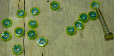
I made some mount bushings for the ECM by using 3/16" polyurethane fuel
line (blue) to match the AN3 bolt, inserted into 5/16" Tygon fuel line,
to match the OD of the grommets. Then I used a razor to cut off
little pieces about 3/16" long, as evenly as I could. It's
surprising how hard it is to make perfectly square cuts in the hose.
I made numerous ones, and picked out the best 4. This will give me
a flexible standoff for the 4 ECM mount bolts.
Here are
the mounts for the ECM backing plate, after I trimmed the ears off the
plate. I found it much better to take the cover and PC board off and
just work with the backing plate. Washers go on top of the rubber
spacers here, then it all gets bolted to nutplates in the RT fwd top
fuselage rib.
Here's
the ECM backing plate, bolted to the F745R rib. The wires going off the LT
in the pic are the wires for the LT side. You can see what I rat's
nest I am left with here in the wiring harness.
Here is
the ECM mounted to the outboard side of the F745R rib, as well as the oxygen sensor relay. I looked at Carsten Schanche's ECM mount, and realized I should probably add a stiffener
to the other side of the rib.
This is
how Carsten mounted his ECM, in the INside of the F745R rib. In hindsight, I should have made
stiffeners with my ECM installation, as well as with some of the other
nutplates I've put in the firewall recently. I'll have to add some.
Carsten's gold anodizing looks cool, too.
Jan 3 - Finish ODB mount plate.
Received MSC (silicone tubing) and McMaster-Carr (split tubing) orders.
Put fuel line cross together. Made standoffs for fuel line cross.
Made firewall backing plate for a stiffer mounting of the filter and cross.
Drilled lightening holes in backing plate. Update web site
6.5 hr + 1.0 hr doc
I got
my order of split tubing (5 lifetime supplies) from McMaster-Carr and a
couple rolls of silicone tubing from MSC.
I made
a cutout to start building a mount for the ODB connector.
Here
is the completed ODB connector mount plate. To match the right thickness for what
the connector was designed to be mounted in, I made a main plate of 0.063"
and added a backing plate of 0.040", then riveted the 2 plates together.
I will mount this under the panel somewhere.
Here is the assembled cross fitting for the fuel pressure transducer and the
low fuel pressure switch. After looking at pics of Carsten's work, I
decided to remove the Andair firewall fuel filter and put in a backing plate
behind the firewall for these 2 items. The 2 Adel clamps will mount to
1/2" diameter 0.560" long spacers I made on the lathe.
This is the front view of the backing plate I made for the Andair firewall
fuel filter and plumbing cross. The firewall was pretty flexy without
it. I screwed up on a couple of the rivet hole placements, but I
should be able to save it OK.
Here
are the FWF fuel parts. I made the 2 bushings on the RT to use to
mount the plumbing cross to the firewall with Adel clamps. The sheet
metal is the backing plate for all this.
Jan 4 - Got email from Jan.
He says it's OK to cut the wiring harness as necessary to make a good fit
for my installation. Debur, dimple, prime, rivet backing plate.
Install Andair firewall fuel filter, plumbing cross, and hose between filter
and cross. Update web site. 3.5 hr +
1.0 hr doc
Here is the Andair firewall fuel filter plumbed to the AN plumbing cross for
the fuel pressure sender and low fuel pressure switch. I gave quite a
bit of thought to a plumbing arrangement that would let me open up the
Andair filter without disconnecting the fuel lines. By using this half
loop in the 3/8" FI hose, I can do that. I could have used different
nipple angles and gone more directly with much shorter hose, or with hard
aluminum tubing, but then it
would have been hard to twist the Andair end to open it up for cleaning.
At the top, the hose is just stuck on there temporarily, until I am done
working on the SC-IC tubing. There will be an Adel clamp in the middle
of this loop, after I complete the SC-IC duct tubing.
Jan 5 - Received supercharger
overpressure blowoff valve from Jan. Update web site
1.0 hr doc
Jan 6 - working on finalizing my
FWF fuel plumbing. Plan mounting for SC-IC blowoff valve.
Drill hole in IC duct for blowoff valve and take it to welding shop. I
got a note from my friend Matt Brandes, who is building a RV-9A in Kansas.
He noticed that I will have a hard time riveting my fwd top skin on because
the ECM mounting will be in the way of bucking the rivets. I
hadn't thought of that - another reason I should have mounted the ECM on the
other side of that rib, like Carsten did. Well, I guess I'll have to
remove the ECM when I go to rivet that top skin. Worked more on FWF
fuel plumbing, then had second thoughts about a couple of the ways I did
things. Posted questions to list on whether things are OK or
not. 3.5 hr
Here
is the installed FWF fuel plumbing. I now wonder if I should put the
transition from aluminum line to 5/16 FI hose at "A" on the engine frame,
rather than on the engine, where it is now, as detailed below. I am
also having second thoughts about the way I plumbed the connection between
the Andair firewall fuel filter and the AN cross fitting. I made it so
it's a 1/2 loop of 3/8" FI hose, so I can open the Andair filter without
disconnecting anything (see Jan 4 pic). It's
disconnected right now, as I had to remove part of the SC-IC tube (with the
wastegate) to send out for more welding (blowoff valve). But now I
wonder if I should have just made the connection with a short piece of
aluminum tubing. The question is whether or not it's bad to
loosen and tighten the AN tubing nut every 100 hr inspection.
This view, on the LT top of the engine, looking aft, is of the transition I
made to go from the hard aluminum fuel line to the 5/16" FI hose. I am
now wondering if I made a mistake in having a solid line from the frame to
the engine, and wondering if I should move the transition over to the RT in
this pic, so the transition is mounted on the engine frame, rather than on
the engine.
This is the Bosch supercharger pressure relief valve Jan sent me.
I removed the piece of intercooler plumbing that contains the wastegate, and
sent it and this out for welding. Jan says the perpendicular part is
the outlet, and if I connect the small connector, barely visible at the LT
end of pic, to the intake manifold, it will also open the valve when the
throttle is closed.
Jan 7 - Spent all morning
rebuilding the fuel pump on the 100 gallon fuel transfer tank I bought
at a recent auction. I plan to use the tank to supply motor fuel
to my plane at the airport, because they only have avgas there.
Reworked the fuel line transition from the frame to the engine, so the
connection is flexible, not solid. Update web site
1.5 hr + 1.0 hr doc
Jan 8 - Finish redoing fuel line
transition from frame to engine. Started laying out fuel line from
fuel pumps to Andair firewall fuel filter. Did some tool cleanup and
went back to straightening out the wiring. I need to order some
connectors, so I can do more wiring work.
2.0 hr
Here is the redone transition from solid aluminum lines at the frame to
rubber hose at the engine. This should work fine. I
was also advised to get some fire sleeve for this, so I ordered some from
Wicks. The Adel clamp at LT is temporary - it's a WDG-10 and I am
waiting for the correct WDG-9 in my Wicks order. My fuel regulator
plumbing is also waiting for those WDG-9 clamps. The orange paint on
the AN nut tells me the connection is tightened and, hopefully, done with.
This 3-pin connector is on the same part of the wiring harness as the 2-pin
connector for the tumble generator. I asked Jan what this is for, as
it appears to be modified by Eggenfellner, presumably for some reason.
I subsequently figured out that it goes to a SECOND connector on the tumble
generator.
Jan 9 - Place Wicks order.
Put together Waytek Wire order. More wire harness straightening and
organizing. Trying to figure out where & how to mount the tumble
generator. Start making rib brace for F745R rib. Update web site
2.5 hr + 1.0 hr doc
The RAD FAN wires are not used, so I just made sure they are labeled, in
case of later need.
I added labels to some of the installed wiring harness components.
Power comes in on the large white wire on the RT. It is spliced into 5
outputs. An inch later, the large white output splits again into 3 more. 3-4
inches later, the large white splits out again into a small white, blu/white,
yellow/red, & big white. Big white then goes a few more inches down off the
picture and Ys into a yellow/blue, which Ys again into 2 yellow/blue, and so
on. It seems to me that it would be a whole lot neater & simpler if all the
wires needing power went into a terminal block that supplied power out where
it’s needed. I sent Jan an email & asked about this. I also
asked about the use of the blue & green tape, shown in the circle.
Jan later said the blue/green tape is original Subaru. Jan & Gary both
suggested leaving the harness the way it is, rather than cutting all
those power leads and running them to a distribution block.
Jan 10 - Pick up intercooler duct
from welding shop. Installed a rib brace for the RT F745 rib, to
reinforce the ECM mounting. Update web site
0.75 hr + 1.0
hr doc
Here is the wastegate section of the SC-IC tubing, with the new pressure
relief valve adapter welded on.
Jan 14 - it's been about 40
degrees the last several days. It's 50 degrees today & lots of
condensation everywhere. Everything in my steel barn is dripping
wet. I used a paint strainer to strain the coolant I had drained
from the engine, and then refilled to coolant tank. I barely got
it back in, even though I had lost some due to spillage, so that will
have to be filled more once the engine runs and the coolant circulates.
There was plenty of gritty-looking stuff in the bottom of the container.
Where did THAT come from? All the containers I used were carefully
washed and wiped before putting the coolant in them. It must
have some from the system. Not good. Sure glad I used the
paint filter before putting it back into the system. Put away
another order from Wicks. Used the WDG-9 Adel clamps I got from
Wicks to finish installing the 5/16" fuel lines, both incoming and at
the fuel pressure regulator. Installed the pressure relief valve
onto the intercooler plumbing. 3.0 hr
Jan 15 - It was 50 degrees
yesterday. Today, it's single digits, snowing, and the wind is
howling. Cleaned up workbench, finished installing fuel pressure
regulator and Adel clamps. Spent some time looking at
brake lines and
EFIS mounting. Looking over my
muffler mounting, and decided to add an 18" extension to each pipe.
This will put the muffler exhaust exits back behind the wing spar. It
will keep heat away from the fuel pumps
(they would have been right under the pumps). It should lessen
cabin noise some. It will put the Lord mounts for the mufflers back
just fwd of the wing spar, rather than right underfoot. It will give
me a bit more play and flex in mounting the mufflers
so they’re not so tight to the fuselage skin.. Laid out
mounting locations. Worked on fuel line from pumps to Andair firewall
filter. Pondering heater installation. In hindsight, I think I
should have installed it with the outlets pointing down, as Carsten and
others have done it. At the time, it seemed natural to have them
pointing up. Oh well... It's so cold out, I have to keep the
heater blasting constantly. By 5:00, it was zero outside.
4.0 hr
Jan 16 - Took my 18" pieces of
stainless steel tubing to a muffler shop, and he expanded the end of each so
they will slip nice & snug over the aft end of the header pipes.
Received and put away Waytek Wire order. Temporarily installed the RT
muffler, with 18" extension. It looks good, and should work
well. 0.75 hr
These are the kind of overlapping wire splices Jan recommends for engine
wiring harness work. Very small & secure. They get covered with
heat shrink tubing that has sealant inside. The crimper for them looks
like a slightly larger than normal Molex crimper.
A muffler shop expanded the ends of 2 of the pieces of stainless steel
tubing I got from Burns Stainless.
And this is what it looks like with the extension installed. I think
this will work well. I asked Jan his recommendation for clamping the
extension/header joint, and he is going to send me a couple clamps, like
those used at the extension/muffler joint.
Jan 17 - I'm also working on
avionics again, as well as some
fuselage work. Update web site
1.0 hr doc
Jan 18 - temps back in the 50s
again and raining. It went from 50s to zero, snowed a foot, and
back to 50s in the last few days. Even if the plane was done, it seems
there are not that many decent VFR flight days here.
 I made some mount bushings for the ECM by using 3/16" polyurethane fuel
line (blue) to match the AN3 bolt, inserted into 5/16" Tygon fuel line,
to match the OD of the grommets. Then I used a razor to cut off
little pieces about 3/16" long, as evenly as I could. It's
surprising how hard it is to make perfectly square cuts in the hose.
I made numerous ones, and picked out the best 4. This will give me
a flexible standoff for the 4 ECM mount bolts.
I made some mount bushings for the ECM by using 3/16" polyurethane fuel
line (blue) to match the AN3 bolt, inserted into 5/16" Tygon fuel line,
to match the OD of the grommets. Then I used a razor to cut off
little pieces about 3/16" long, as evenly as I could. It's
surprising how hard it is to make perfectly square cuts in the hose.
I made numerous ones, and picked out the best 4. This will give me
a flexible standoff for the 4 ECM mount bolts.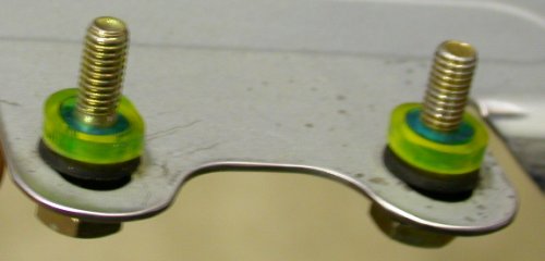 Here are
the mounts for the ECM backing plate, after I trimmed the ears off the
plate. I found it much better to take the cover and PC board off and
just work with the backing plate. Washers go on top of the rubber
spacers here, then it all gets bolted to nutplates in the RT fwd top
fuselage rib.
Here are
the mounts for the ECM backing plate, after I trimmed the ears off the
plate. I found it much better to take the cover and PC board off and
just work with the backing plate. Washers go on top of the rubber
spacers here, then it all gets bolted to nutplates in the RT fwd top
fuselage rib.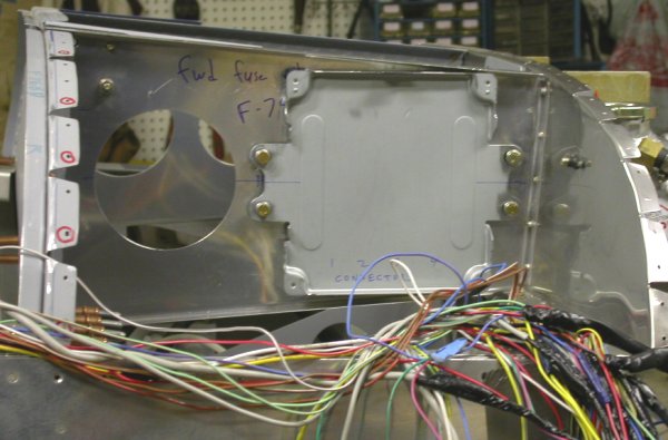 Here's
the ECM backing plate, bolted to the F745R rib. The wires going off the LT
in the pic are the wires for the LT side. You can see what I rat's
nest I am left with here in the wiring harness.
Here's
the ECM backing plate, bolted to the F745R rib. The wires going off the LT
in the pic are the wires for the LT side. You can see what I rat's
nest I am left with here in the wiring harness. 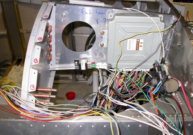 Here is
the ECM mounted to the outboard side of the F745R rib, as well as the oxygen sensor relay. I looked at Carsten Schanche's ECM mount, and realized I should probably add a stiffener
to the other side of the rib.
Here is
the ECM mounted to the outboard side of the F745R rib, as well as the oxygen sensor relay. I looked at Carsten Schanche's ECM mount, and realized I should probably add a stiffener
to the other side of the rib.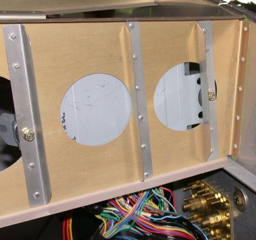 This is
how Carsten mounted his ECM, in the INside of the F745R rib. In hindsight, I should have made
stiffeners with my ECM installation, as well as with some of the other
nutplates I've put in the firewall recently. I'll have to add some.
Carsten's gold anodizing looks cool, too.
This is
how Carsten mounted his ECM, in the INside of the F745R rib. In hindsight, I should have made
stiffeners with my ECM installation, as well as with some of the other
nutplates I've put in the firewall recently. I'll have to add some.
Carsten's gold anodizing looks cool, too.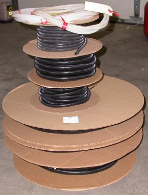 I got
my order of split tubing (5 lifetime supplies) from McMaster-Carr and a
couple rolls of silicone tubing from MSC.
I got
my order of split tubing (5 lifetime supplies) from McMaster-Carr and a
couple rolls of silicone tubing from MSC.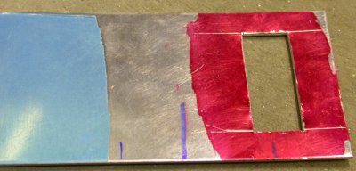 I made
a cutout to start building a mount for the ODB connector.
I made
a cutout to start building a mount for the ODB connector.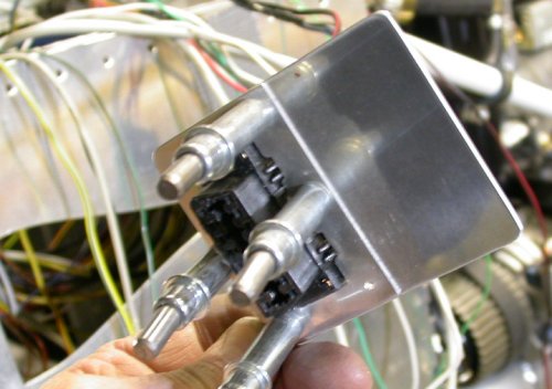 Here
is the completed ODB connector mount plate. To match the right thickness for what
the connector was designed to be mounted in, I made a main plate of 0.063"
and added a backing plate of 0.040", then riveted the 2 plates together.
I will mount this under the panel somewhere.
Here
is the completed ODB connector mount plate. To match the right thickness for what
the connector was designed to be mounted in, I made a main plate of 0.063"
and added a backing plate of 0.040", then riveted the 2 plates together.
I will mount this under the panel somewhere.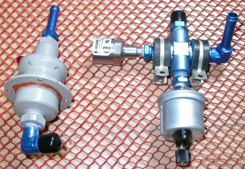 Here is the assembled cross fitting for the fuel pressure transducer and the
low fuel pressure switch. After looking at pics of Carsten's work, I
decided to remove the Andair firewall fuel filter and put in a backing plate
behind the firewall for these 2 items. The 2 Adel clamps will mount to
1/2" diameter 0.560" long spacers I made on the lathe.
Here is the assembled cross fitting for the fuel pressure transducer and the
low fuel pressure switch. After looking at pics of Carsten's work, I
decided to remove the Andair firewall fuel filter and put in a backing plate
behind the firewall for these 2 items. The 2 Adel clamps will mount to
1/2" diameter 0.560" long spacers I made on the lathe.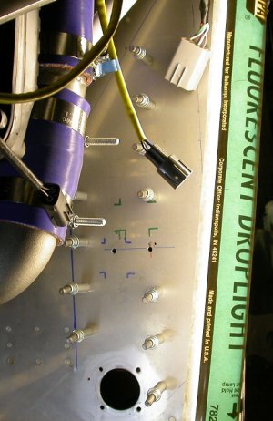 This is the front view of the backing plate I made for the Andair firewall
fuel filter and plumbing cross. The firewall was pretty flexy without
it. I screwed up on a couple of the rivet hole placements, but I
should be able to save it OK.
This is the front view of the backing plate I made for the Andair firewall
fuel filter and plumbing cross. The firewall was pretty flexy without
it. I screwed up on a couple of the rivet hole placements, but I
should be able to save it OK. 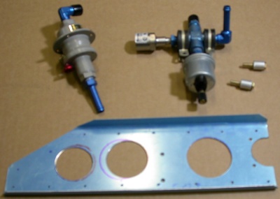 Here
are the FWF fuel parts. I made the 2 bushings on the RT to use to
mount the plumbing cross to the firewall with Adel clamps. The sheet
metal is the backing plate for all this.
Here
are the FWF fuel parts. I made the 2 bushings on the RT to use to
mount the plumbing cross to the firewall with Adel clamps. The sheet
metal is the backing plate for all this.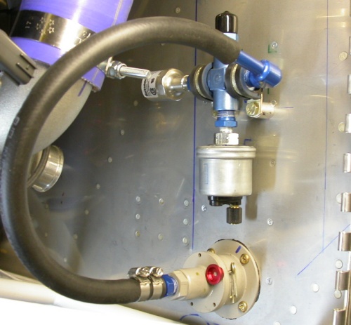 Here is the Andair firewall fuel filter plumbed to the AN plumbing cross for
the fuel pressure sender and low fuel pressure switch. I gave quite a
bit of thought to a plumbing arrangement that would let me open up the
Andair filter without disconnecting the fuel lines. By using this half
loop in the 3/8" FI hose, I can do that. I could have used different
nipple angles and gone more directly with much shorter hose, or with hard
aluminum tubing, but then it
would have been hard to twist the Andair end to open it up for cleaning.
At the top, the hose is just stuck on there temporarily, until I am done
working on the SC-IC tubing. There will be an Adel clamp in the middle
of this loop, after I complete the SC-IC duct tubing.
Here is the Andair firewall fuel filter plumbed to the AN plumbing cross for
the fuel pressure sender and low fuel pressure switch. I gave quite a
bit of thought to a plumbing arrangement that would let me open up the
Andair filter without disconnecting the fuel lines. By using this half
loop in the 3/8" FI hose, I can do that. I could have used different
nipple angles and gone more directly with much shorter hose, or with hard
aluminum tubing, but then it
would have been hard to twist the Andair end to open it up for cleaning.
At the top, the hose is just stuck on there temporarily, until I am done
working on the SC-IC tubing. There will be an Adel clamp in the middle
of this loop, after I complete the SC-IC duct tubing.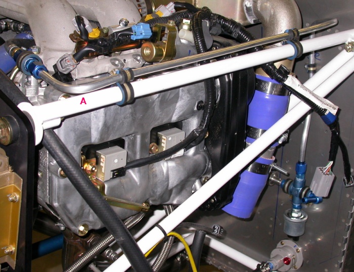 Here
is the installed FWF fuel plumbing. I now wonder if I should put the
transition from aluminum line to 5/16 FI hose at "A" on the engine frame,
rather than on the engine, where it is now, as detailed below. I am
also having second thoughts about the way I plumbed the connection between
the Andair firewall fuel filter and the AN cross fitting. I made it so
it's a 1/2 loop of 3/8" FI hose, so I can open the Andair filter without
disconnecting anything (see
Here
is the installed FWF fuel plumbing. I now wonder if I should put the
transition from aluminum line to 5/16 FI hose at "A" on the engine frame,
rather than on the engine, where it is now, as detailed below. I am
also having second thoughts about the way I plumbed the connection between
the Andair firewall fuel filter and the AN cross fitting. I made it so
it's a 1/2 loop of 3/8" FI hose, so I can open the Andair filter without
disconnecting anything (see 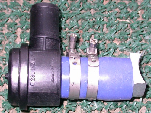 This is the Bosch supercharger pressure relief valve Jan sent me.
I removed the piece of intercooler plumbing that contains the wastegate, and
sent it and this out for welding. Jan says the perpendicular part is
the outlet, and if I connect the small connector, barely visible at the LT
end of pic, to the intake manifold, it will also open the valve when the
throttle is closed.
This is the Bosch supercharger pressure relief valve Jan sent me.
I removed the piece of intercooler plumbing that contains the wastegate, and
sent it and this out for welding. Jan says the perpendicular part is
the outlet, and if I connect the small connector, barely visible at the LT
end of pic, to the intake manifold, it will also open the valve when the
throttle is closed.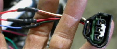 This 3-pin connector is on the same part of the wiring harness as the 2-pin
connector for the tumble generator. I asked Jan what this is for, as
it appears to be modified by Eggenfellner, presumably for some reason.
I subsequently figured out that it goes to a SECOND connector on the tumble
generator.
This 3-pin connector is on the same part of the wiring harness as the 2-pin
connector for the tumble generator. I asked Jan what this is for, as
it appears to be modified by Eggenfellner, presumably for some reason.
I subsequently figured out that it goes to a SECOND connector on the tumble
generator.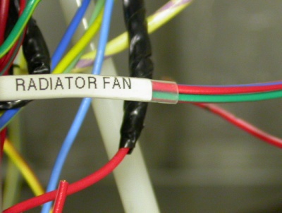 The RAD FAN wires are not used, so I just made sure they are labeled, in
case of later need.
The RAD FAN wires are not used, so I just made sure they are labeled, in
case of later need.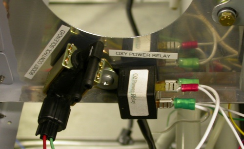 I added labels to some of the installed wiring harness components.
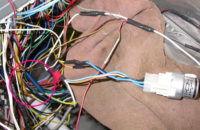 Power comes in on the large white wire on the RT. It is spliced into 5
outputs. An inch later, the large white output splits again into 3 more. 3-4
inches later, the large white splits out again into a small white, blu/white,
yellow/red, & big white. Big white then goes a few more inches down off the
picture and Ys into a yellow/blue, which Ys again into 2 yellow/blue, and so
on. It seems to me that it would be a whole lot neater & simpler if all the
wires needing power went into a terminal block that supplied power out where
it’s needed. I sent Jan an email & asked about this. I also
asked about the use of the blue & green tape, shown in the circle.
Jan later said the blue/green tape is original Subaru. Jan & Gary both
suggested leaving the harness the way it is, rather than cutting all
those power leads and running them to a distribution block.
Power comes in on the large white wire on the RT. It is spliced into 5
outputs. An inch later, the large white output splits again into 3 more. 3-4
inches later, the large white splits out again into a small white, blu/white,
yellow/red, & big white. Big white then goes a few more inches down off the
picture and Ys into a yellow/blue, which Ys again into 2 yellow/blue, and so
on. It seems to me that it would be a whole lot neater & simpler if all the
wires needing power went into a terminal block that supplied power out where
it’s needed. I sent Jan an email & asked about this. I also
asked about the use of the blue & green tape, shown in the circle.
Jan later said the blue/green tape is original Subaru. Jan & Gary both
suggested leaving the harness the way it is, rather than cutting all
those power leads and running them to a distribution block.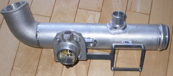 Here is the wastegate section of the SC-IC tubing, with the new pressure
relief valve adapter welded on.
Here is the wastegate section of the SC-IC tubing, with the new pressure
relief valve adapter welded on.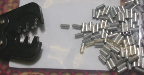 These are the kind of overlapping wire splices Jan recommends for engine
wiring harness work. Very small & secure. They get covered with
heat shrink tubing that has sealant inside. The crimper for them looks
like a slightly larger than normal Molex crimper.
These are the kind of overlapping wire splices Jan recommends for engine
wiring harness work. Very small & secure. They get covered with
heat shrink tubing that has sealant inside. The crimper for them looks
like a slightly larger than normal Molex crimper. 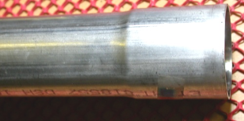 A muffler shop expanded the ends of 2 of the pieces of stainless steel
tubing I got from Burns Stainless.
A muffler shop expanded the ends of 2 of the pieces of stainless steel
tubing I got from Burns Stainless.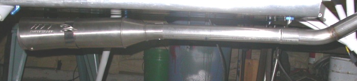 And this is what it looks like with the extension installed. I think
this will work well. I asked Jan his recommendation for clamping the
extension/header joint, and he is going to send me a couple clamps, like
those used at the extension/muffler joint.
And this is what it looks like with the extension installed. I think
this will work well. I asked Jan his recommendation for clamping the
extension/header joint, and he is going to send me a couple clamps, like
those used at the extension/muffler joint.