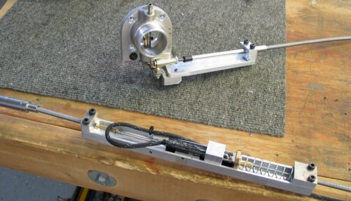
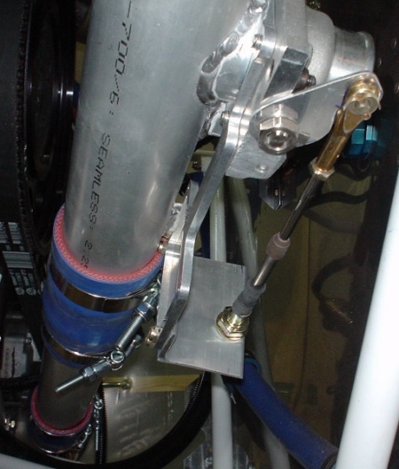
 This is Robert Paisley's prototype throttle and wastegate controller.
ENGINE WORK May, 2006
May 8 - queried Robert Paisley as to when I can get the throttle/wastegate assy he's been developing. I've been waiting since last summer for a solution to the wastegate control. I emailed Robert the first of Feb, and he said he was still developing one. Now he says it'll still be months before he gets it done. I think he is now running an H6 in his plane (Jan's new "only" product), and I suspect the STi interest is waning on both his part and Jan's. I need a workable wastegate so I can put the last piece of intercooler plumbing in, and I need a throttle so I can start the engine. I got Gary Newsted's throttle, but Jan had dumped his previous wastegate control design (without any notice or providing us with any alternative), so I am stuck with Robert's consolidated throttle/wastegate design. At least Robert says I can send him Gary's throttle for credit, if he ever gets the damn thing done & ready to sell. Jan had also posted a reply that suggested moving ahead on my own, rather than trying to wait for Robert. By the time Robert gets around to releasing the product, all interest in it will have evaporated. Update web site 1.0 hr doc
This is Robert Paisley's prototype throttle and wastegate controller.
May 10 - back to the engine wiring mess. Installed fuel plumbing from pumps to filter. Replace fuel pumps plumbing input with a more compact one. Reconfigure fittings on Andair fuel selector valve. 1.5 hr
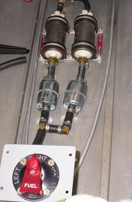 Here are the installed fuel pumps, with the new, smaller, lighter inlet
splitter I made.
Here are the installed fuel pumps, with the new, smaller, lighter inlet
splitter I made.
May 11- Replace fuel pumps filter inlet plumbing & fiddle with fuel plumbing 1.5 hr
May 12 - pondering replacing/bracing fuel line from pumps to firewall filter. Took it to Steve Keen at Ascutney Aviation to get his opinion. He said just make a simple brace from a tie wrap and rubber hose. Install & tighten fuel line. Start pondering throttle and wastegate control setups. Should I buy a quadrant or make my own? I'd like to incorporate the MT prop control into the throttle. Back to untangling engine wiring harness rat's nest. 4.25 hr
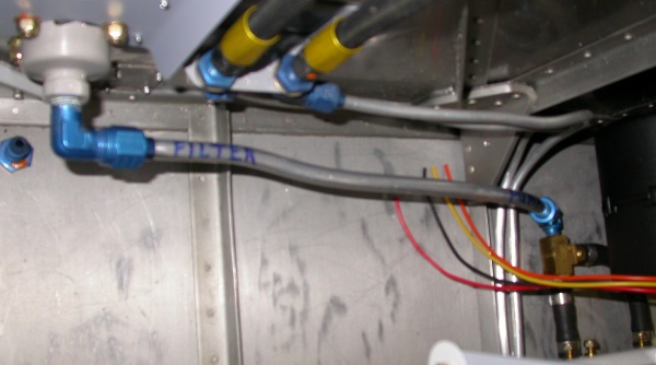 This is the fuel line from the pumps to the firewall fuel filter. I
wondered if it needed to be braced. Steve said it was fine, although I
could add a simple brace, made from a piece of hose and a tiewrap, to the
middle of it. This is looking down at the floor, just aft of the
firewall at the top of the picture.
This is the fuel line from the pumps to the firewall fuel filter. I
wondered if it needed to be braced. Steve said it was fine, although I
could add a simple brace, made from a piece of hose and a tiewrap, to the
middle of it. This is looking down at the floor, just aft of the
firewall at the top of the picture.
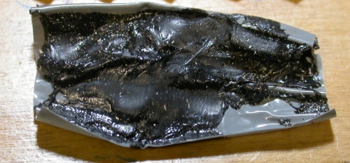 This
is some sealant tape that was used on some of the splices in the wiring
harness. It looks like pretty good stuff, for when you can’t get
heatshrink tubing onto an existing connection. It has a plastic outer layer,
and a very gooey inner layer. It doesn’t stick to other things, but it loves
to stick to itself. This is apparently from Subaru. I
later found out that an equivalent product is 3M's "Electrical Moisture
Sealant", DCI No. 054007-06149. It's (25) 2.5" x 2.5" patches.
This
is some sealant tape that was used on some of the splices in the wiring
harness. It looks like pretty good stuff, for when you can’t get
heatshrink tubing onto an existing connection. It has a plastic outer layer,
and a very gooey inner layer. It doesn’t stick to other things, but it loves
to stick to itself. This is apparently from Subaru. I
later found out that an equivalent product is 3M's "Electrical Moisture
Sealant", DCI No. 054007-06149. It's (25) 2.5" x 2.5" patches.
May 13 - more untangling engine wiring harness. I am cutting selected wires (one at a time), untangling them, then splicing them back together with crimped parallel connectors and double-wall (glue inside) heat shrink tubing. 5.0 hr
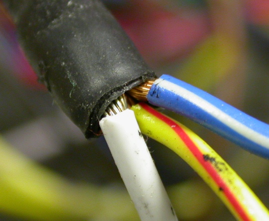 Here is
one of the many splices I uncovered. Whoever did this missed
completely on the heatshrink. These are +12v power leads, too!
Here is
one of the many splices I uncovered. Whoever did this missed
completely on the heatshrink. These are +12v power leads, too!
May 14 - more untangling engine wiring harness mess. Got all the connectors & wires going over to the LT side of the engine separated & neat now. Experimenting with testing the strength of various methods of crimping the parallel connectors I've been using. I still have numerous unlabeled long wires (as opposed to the short ones cut off at various connectors). Sent an email to Eggenfellner list, asking about those wires and about what to do with the now-unused "Airflow Meter Connector". 5.0 hr
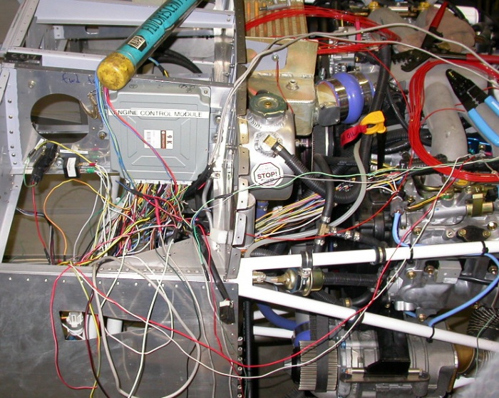 Working on untangling this horrific rat's nest of engine wiring harness.
My first goal is to separate out the 4 connectors that have to go over the
the LT side of the engine. So, I am just separating them out one wire
at a time, untangling the wires as I go.
Working on untangling this horrific rat's nest of engine wiring harness.
My first goal is to separate out the 4 connectors that have to go over the
the LT side of the engine. So, I am just separating them out one wire
at a time, untangling the wires as I go.
May 15 - spent some time emailing Richard Reid and Mickey Coggins, asking about how they'd done their throttle/wastegate control, and putting together an ACS order. I'd have preferred to order from Wicks, but ACS had a much better selection.
The next 4 pictures are how Richard Reid did his throttle and wastegate controller:
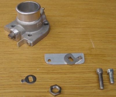 wastegate control valve parts
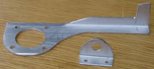 Here is Richard's mounting bracket.
 assembled wastegate control valve
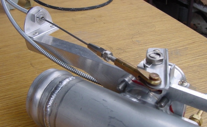
 This is Richard's throttle quadrant and wastegate control assy, using Gary
Newsted's electronic throttle control module and a Van's quadrant.
This is Richard's throttle quadrant and wastegate control assy, using Gary
Newsted's electronic throttle control module and a Van's quadrant.
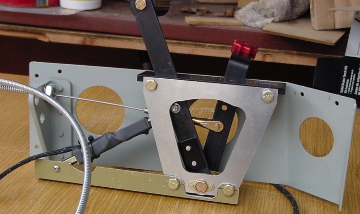
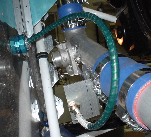 This is how Mickey Coggins implemented Richard's design.
 another view of Mickey's wastegate control
May 16 - Ordered throttle/wastegate control parts from ACS. Debating whether or not to attack the endless series of Ys on the +12v leads - going to dozens of places. Ordered more wiring supplies from SteinAir, including a distribution block for resolving the multitude of +12v spliced wires in the harness. Update web site 4.0 hr doc
May 18 - Exchanged some emails with Jan about wiring questions. People were talking about a new optional prop control bracket, so I asked about that. I found it'd cost $100 including shipping, so I decided to stick with the one I have. Later, Jan offered to send me one. VERY nice of him to do that! I may bitch about Jan sometimes, and there are things about the package I am not happy about, but he's clearly a good guy trying hard to do a good job. Still trying to find out where the 6 long unlabeled wires are supposed to go. Sent Jan some emails and pics about it. Later found out they go to the THROTTLE. I also decided to finish up the fuel plumbing. I'd like to START this engine sometime! After I last tore out what I had and reinstalled the brake lines on the bottom and the fuel return lines in the middle, way back in November, 2003, I never got around to redoing the top fuel supply lines. So, I dove into that, and started making one of the lines. I ran into trouble right away. I don't know how Gary did it, but on mine, the top hole in the gear leg frame is partially blocked by the flange on the frame. The 3/8" line used to run through the middle hole OK, and I MAY have used a thinner, more flexible line through the upper hole, but this 3/8" through that upper hole is going to be a bear. Despite all the talk, even on the Eggenfellner list, about how it's so wrong to use rubber fuel line from the wings, I don't see what the heck difference it makes. I have to use it, under high pressure, to and from the fuel rails on the engine. I have to use it to and from the fuel pumps. So why not simplify life and run it from the wing tanks to the fuel selector valve, too? I think I will do that. 2.0 hr
May 19 - Received my ACS order, and I was immediately disappointed in their 05-00699 throttle quadrant. It doesn't use any non-metal parts, so the friction adjustment causes the levers to scrape metal-against-metal, against the side of the frame. It looks great, and was much more expensive than other options, but the way the maker did the friction adjuster makes it a bad execution. When the friction adjuster is set to a reasonable level, the levers scrape and grind against the frame. It's going back Monday. ACS' much cheaper 05-15920 quadrant, with phenolic blocks, works much more smoothly. I guess I'll need to order a 2-lever version of that (or from Wicks - cheaper). Update web site 2.0 hr doc
May 21 - tested how wastegate control works. Found that the butterfly valve does not completely seal. Looked into alternate electric solenoid-operated valves. Emailed Eggenfellner list with questions about wastegate sealing and solenoid valves. Made a couple attempts to get RT side 3/8" fuel feed line made & installed. 3.0 hr
May 22 - finish and adjust RT fuel feed plumbing 1.0 hr
May 24 - received the prop controller bracket from Jan. It was VERY nice of him to send this to me, as it'd cost $100 if I ordered it. Thanks Jan! Installed LT side fuel feed plumbing. It went rather smoothly. I found that the assembly sequence is important, to get all the AN818 nuts to go onto the fuel control valve, due to minor (and seemingly uncorrectable) differences in alignment between each fuel line and each AN fitting on the valve. I leave the valve loose, not fastened to the spar, then I do the LT return, RT return, center return, LT feed, RT feed, in that order. Then fasten down the valve to the spar. The nuts all go on smoothly if I do it that way. I also checked in the AC-xxx what the torque should be for each of these AN818 nuts. It also mentioned that I should lubricate the threads with hydraulic fluid (presumably ATF will work OK) before installing the nuts. 2.0 hr + 1 hr doc
May 26 - drilled coolant cap for safety wire. Laid out power distribution block and drilled holes in firewall to mount it. Started cutting the mess of spliced +12v ECM leads and installing them one at a time to the distribution block. 3.75 hr
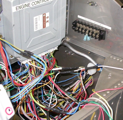 This is where I decided to mount the +12v ECM power distribution block; on
the firewall, near the ECM. Even though this wiring harness STILL
looks like a rat's nest, I've already pulled out most of the tangles.
Only the +12v leads remain to be untangled, and they are a big intertwined
mess.
This is where I decided to mount the +12v ECM power distribution block; on
the firewall, near the ECM. Even though this wiring harness STILL
looks like a rat's nest, I've already pulled out most of the tangles.
Only the +12v leads remain to be untangled, and they are a big intertwined
mess.
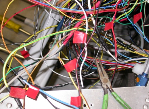 I marked each +12v lead with red tape as I cut it away from the harness.
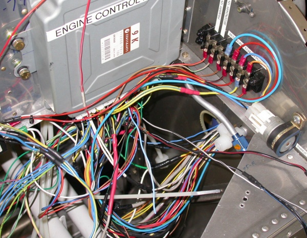 Here, I am just starting to connect the leads to the distribution block.
You can see where & how I mounted one of the relays for the harness, clamped
to the firewall on the RT side of the pic.
Here, I am just starting to connect the leads to the distribution block.
You can see where & how I mounted one of the relays for the harness, clamped
to the firewall on the RT side of the pic.
May 27 - continue cutting +12v ECM wires and connecting them to the distribution block, and securing all the other wiring harness parts, like the tumble generator. 9.0 hr
May 29 - prime, label, and mount ODB connector mount. Lace up wires to distribution block. Continue lacing and organizing engine wiring harness. Tested some old 28 volt Air Force indicators I had floating around, and checked ACS catalog to get some 12v bulbs for them. 8.0 hr
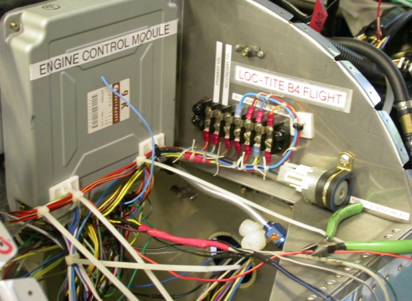 Here, I've got all the +12v ECM leads now going to the distribution block,
and the rest of the wiring harness is starting to look like wires all going
in the same direction. The screws in the distribution block will all
be redone with Loc-Tite on the threads and the heads covered with liquid
electrical tape, when I am sure it's complete.
Here, I've got all the +12v ECM leads now going to the distribution block,
and the rest of the wiring harness is starting to look like wires all going
in the same direction. The screws in the distribution block will all
be redone with Loc-Tite on the threads and the heads covered with liquid
electrical tape, when I am sure it's complete.
BACK TO MY RV BUILDER'S HOME
BACK TO BRIAN'S HOME