Aug 1 - spent most of the
afternoon updating the
Eggenfellner Installation Manual. Later,
drilled and installed the PSRU vent bottle plug.
0.25 hr
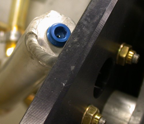
At
Oshkosh, I looked at Tom Moore's plane and saw what is supposed to be done
with the threaded hole at the top of the PSRU vent bottle. It needs a
plug with a tiny hole drilled in it. Jan didn't include
this plug with my PSRU vent bottle, so I ordered one from Wicks, and drilled
a #55 hole through it. Note I've also replaced the Eggenfellner-supplied,
too-short, PSRU vent bottle mount screws, added washers, and replaced the supplied nylon
locknuts with all-steel locknuts. See my
June page for the poor workmanship in
what Eggenfellner sent me.
Robert Paisley
did this differently; he ran a piece of flexible tubing from
the top of the bottle into the side of the engine vent hose.
Aug 2 - more
Eggenfellner Installation Manual
updates, update web site 1.0 hr doc
Aug 3 - more Eggenfellner Installation Manual
updates - I really need to get back to working on my own plane and web
site.
Aug 4 - updating the web site from New
Hampshire International Speedway. I've been dumping annotated
pictures in all last month, but it's been a long time since I updated the
daily log or the INDEX. Working on that now.
5.5 hr doc
Aug 5 - Eggenfellner Installation Manual
updates from NHIS
Aug 6 - Eggenfellner Installation Manual
updates from NHIS.
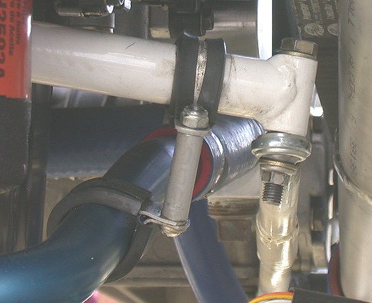
I had been looking at my engine and thinking about how I can better support
a very floppy coolant tubing going to the LT radiator. This is how
Robert Paisley did his, and it looks like a fine way to do mine. I'll
have to order the parts, as the FWF didn't come with the parts to do this.
Aug 7 - Back from NHIS (my lap times sucked, no
crashes), so I did some practice TIG welding on little pieces I'd cut off
the 1.75" stainless steel tubing I got from Burns.
2.0 hr
Practicing welding 0.050" stainless steel tubing from Burns. I started
at 50a, as on the RT, and ended up at 30a, as on the LT. Not too
great, but should be good enough to tack things in place for a pro to finish
the job. I'll be doing some more practice later. I'm also still
trying to decide exactly how I want to modify things to get the mufflers to
fit.
Aug 8 - a couple more hours practicing TIG
welding on stainless steel tubing 2.0 hr
Aug 9 - Decided to start laying out the
heater. It was immediately apparent that there are space conflicts
between the heater and the fuel pumps assy, as well as between the
heater and the firewall recess. When I put the firewall recess in, I
was advised to go with the stock recess, rather than a flat panel.
But the recess forces me to mount the heater so low it interferes with
the fuel pumps assy that is longer than stock after my previous mods
there. TIP: if you're using an Eggenfellner engine (or any
engine that does not NEED the firewall recess, I strongly recommend that
you get and use the flat replacement panel, instead. 0.75 hr
The fuel pumps assy had to be shoved way back to fit the heater in there.
I can't get the heater much higher because the firewall recess sticks
out. I suppose even if I'd put a flat panel in there, instead, I'd
still have interference with the F601E angle that goes across the bottom.
Aug 10 - Marked the header nuts for safety
wire drilling, whenever I decide what to do about the muffler mounting.
However, on that front, Gary Newsted is now saying "The
Lord mounts are primarily for vibration control not for carrying weight,
although they should be good for about 45 lbs. When installing your mounts,
make sure you do not use the mounts to pull the muffler upwards. Use spacers
or tweak your brackets so that there is no weight on the mounts. The headers
are fairly rigid and will support the weight of the muffler/s. The mounts
should not alter the position of the muffler when they are attached, there
there should be no weight or tension on the mounts. The mounts are there to
absorb vibration and they will pick up some amount of load due to deflection
caused by g-forces. If you use these devices to pull the muffler upwards,
you'll end up transmitting excessive noise and vibration into your floor
panel and eventually you'll tear the mount apart.". I added
that info to the Eggenfellner manual. If that's the case, and I'd
never heard that before, then perhaps my mufflers aren't too bad where they
are. I'd assumed the Lord mounts were there to lift and completely
support the muffler. Then, I went back to working on the heater
layout. I made and laid out a heater pattern, so I can try to install
the heater as high and to the right as it will fit in the center space.
That way, I may be able to at least partially run the fuel plumbing under
the heater. I noted that the heater's own fasteners are stainless
steel, while the mount fasteners, apparently supplied by Eggenfellner, are
cheap looking ordinary steel hardware store screws and washers. The
heater shutoff valve and shutoff valve cable are also el-cheapo discount auto parts store items made in China. I may replace them with
something better, especially the cable. I have had experiences on my
own vehicles using those cheap push-pull "universal choke" cables.
They rust inside easily, and soon start binding. On my tractor, I put
a new one in and soon ended up pulling the damn thing out, and now I just
use my hand to reach up under the hood & set the choke by hand when I start
it. So, I sure as hell don't want cheap, unreliable crap like that on
my plane. I looked in my ACS and Wicks catalogs for something better,
but didn't find anything, YET. UPDATE - Jan ended up
saying the heater valve (and thus the cable, too) are no longer needed or
recommended 1.5 hr + 1.0
hr doc
I've used these before, and they are not very reliable or long-lived.
No way am I putting this junk on my plane. I can't believe
Eggenfellner would use such poor quality parts on his FWF.
I made a cardboard pattern from the heater, and used that to lay out for
the heater. I wanted it as high as possible to get away from the
pumps, and as far to the RT as possible, to get away from the brake lines.
I bent a little jog in the fuel return line, just to the RT of the green
cardboard, so the heater will clear that. This looks like where I will
drill the firewall out. But, I want to check the heater installation
part of the Eggenfellner manual before I start cutting.
Aug 11 - I decided that, in order to lower
the pumps so they'll fit in there with the heater, I need to go back to
the original red frame. I'll have to replace the supplied round
head screws with flathead screws and countersink the frame for them, but
I will make that work. That alone will lower the pumps by about
1.5". I'll have to get the screws, plus some to fasten the frame
to the bottom skin, on my next ACS order. I then could see
that the fwd heater vent outlet is going to interfere with that firewall
recess. I need about 2.25" to clear the recess, and the fwd heater
outlet is about 1.5" back from the fwd edge. I now think it was
a big mistake to put that in there, instead of a flat panel.
Read and be forewarned. I will make it work somehow, even if
I have to cut a hole in the recess and put a curved patch in there to
allow for the heater air hose. Drilled the holes for the heater
and mounted it. The mount holes didn't some out exactly right, so
I had to enlarge them a bit. It's a WHOLE lotta fun working in
there, laying on my stomach! I found what appears to be a decent
quality push-pull control cable at ACS for my heater shutoff valve.
2.5 hr
Here's the cabin view of the installed heater. The pumps are just
laying in there, and I will fit them in around the heater next. Man, I
gotta get all that debris vacuumed up in there! It's even worse out
the outer sides.
Here's the fwd firewall view of the installed heater. I don't dare put
the hoses on yet, though, because I am concerned about interference with the
intercooler. So, I still have to wait to install the intercooler
and supercharger before I can put anything else on the firewall. Also,
the heater kit apparently did not come with the tee fittings I will need to
tie these fittings into the heater hose lines.
Aug 12 - I vaguely recalled that the latest
consensus on the Eggenfellner list was that the heater shutoff valve and
cable are no longer recommended. I searched old emails & found this
info. People claim that heat doesn't come out of the heater in the
summer unless the fan is on. So, that's a few (rather junky, I think)
parts I don't need. I updated the
Eggenfellner Install Manual with this info.
0.25 hr + 1.0 hr doc
Aug 14 - Remove heater and open mount holes
a bit for easier mount fitting. There is no wiring diagram with
the heater kit. Hopefully, the wiring diagrams in the manual will
show what the 4 connector leads go to. Continued mounting the
coolant reservoir. Made a 5/8" long spacer for the 1/4" bolt at
the bottom of the reservoir. Installed one end of the heater hose
I had removed earlier due to a defect in the hose. Went to Home
Depot looking for various hardware, including s/s screws for mounting
the heater, and barbed fittings for the heater hoses & for converting
the 5/8" heater hose at the heater to the 1/2" heater hose used in the
rest of the system. 3.5 hr
Aug 15 - I'm still trying to resolve the angle
difference in the coolant reservoir mount. Perhaps I could use a Van's
trailing edge wedge? I also need to ask the Eggie list how they are
converting from 5/8" hose size at the heater to 1/2" for the rest of the
heater hoses. Cleaned up some, enlarged the heater tubing holes in the
firewall, put away yet another ACS order of small parts needed for this
"complete FWF" package. Did a final install on the heater, sealing around the
fittings at the firewall holes. As soon as I did that, I could see
that I'd never get the fwd heater outlet air hose on that way. I took
my rivet gun and pounded an indentation into the firewall recess, to allow
some clearance above the fwd heater outlet. It didn't get me quite
enough, though, so now tomorrow I'll have to pull the sealed-in heater back
off the firewall to pound on the firewall recess some more from a lower
angle. Grrrrr! DON'T install the firewall recess
with an Eggenfellner engine - trust me. I can't see that there's anything at all gained by
having it, and is is a pain with the heater. Get the flat replacement
from Van's if you're putting in an Eggenfellner engine and heater.
Plus I should have mounted the heater 1/2" or even 1/4" lower; then I
wouldn't have to remove the heater to get the last bit of clearance.
3.75 hr
Here's the heater installed and the holes sealed with hi-temp silicone.
No sooner did I get this done than I realized I'd have to take it out again
to hammer the firewall recess in some more from a lower angle than I am able
to with the heater installed. The base of the firewall recess is "very
attractive" now.
This is a closeup of how the angles of the coolant reservoir and the
firewall do not mesh well. At the bottom is a 5/8" long bushing I made
on the lathe, to make the reservoir hang plumb. I ordered some of
Van's trailing edge wedge material to try to get something solid in there.
I also thought about putting a clay dam in there and filling it from the top
with epoxy & microballoons. We'll see how the wedge works out.
Others have made a big bracket to hold the reservoir, but I thought I could
do it simpler and lighter this way.
This pic shows the standoff spacer I made, so the coolant reservoir hangs
plumb.
Here's the coolant reservoir installed as high and to the right as I could
get it, right up next to the brake fluid reservoir. I want to get it
as far as I can from the supercharger and I made the blue alignment line,
but then decided to get it a bit higher at the red line.
Aug 16 - query Eggie list about heater hose 1/2" to
5/8" adapter needed. Mickey pointed out some stuff in McMaster-Carr
and I found another page of good stuff (p. 111). Mickey also
recommended that I try Home Depot, although I went there yesterday and
didn't see much of a selection there or at the local hardware stores.
Ordered yet more small parts from Van's, ACS, Avery Tools to fill in my
"complete FWF package". Another STi customer contacted
me about problems in his alternator installation. To mount the
alternator at the aft of the engine, Jan has put an 8mm stud into a threaded
boss on the block. Unfortunately, the alternator is made with a 10mm
hole for mounting. Jan just stuck the alternator, with the 10mm mount
hole, onto the 8mm stud. The other customer queried him about this &
was told it was OK. The other customer didn't buy this, and asked me
to check mine. SOS - mine had it, too, plus there's a spacer in there
on the 8mm stud with a 1/2" hole in it. It's sloppy and rough, with
absolutely no deburring done to it. The oversized hole in the spacer
doesn't really affect the mounting, but it sure looks sloppy. I made
up a new spacer with an 8mm hole in it, and I made up a bushing to go in the
alternator to bridge the gap between the 8mm stud and the 10mm alternator
hole. I made up 2 sets; one for me and one for the other customer.
I also noted while doing this that the red anodized alternator tension
adjustment arm, like the red anodized fuel pumps frame, has had NO deburring
or smoothing of edges whatsoever. Jan replied to my queries on the
list about the 5/8" to 1/2" adapter. He said he is going to exchange
my heater for one that has 1/2" barbs. That's very good of him;
you can't beat Eggenfellner's customer service, and good customer service
makes everything else work. Update web site.
3.0 + 1.0 hr doc
Aug 17 - There was an email on the E-Subie list a week or 2 ago about NSI
and non-existent responsiveness to customers and a possible reorganization.
Today, I read this on the E-Subie list: I talked to
LeGrande harris on monday and got the skinny on whats going on. LG had
to fire almost every one at NSI. When he started doing some digging he
found something like 250k a year in embezzling,cars and car parts for
personal vehicles,Customer deposits were being pocketed etc,.. Just an
incredibly poorly run business. The only person he kept was Craig
Woolman the guy that actually builds the engines. LG told me his new
payroll will Be less than what Lances daughter and her boyfriend were taking
from NSI. He also told Me they are in the process of putting together
criminal charges. Very dramatic changes for sure but we all knew something
had to be done. I cant remember what the new name of the company was
but they are very well funded and from what I know of LG should be very well
run. I'm sure glad I didn't go for an NSI engine! I
may not be real happy with some things about Jan & his engine, but at least
he isn't ripping customers off and he's always available and responsive.
Apparently Lance at NSI (also the source of the old severe NSI reputation
problems) is no longer with NSI. See the Aug 20 entry for more details
on this from the E-Subie list. Reinstalled alternator with new
bushing and spacer. Removed heater and finished hammering the pss out
of the firewall recess, to make room for the heater fwd duct. It looks
like hell, but it'll work and will not be very visible once this is all
done. There was no point in reinstalling the heater, as Jan is sending
me a new one. 0.75 hr
I made up 2 sets of bushings and spacers to enable a good fit for the
alternator mount system. The spacer on the LT is the one that was
installed. While the 1/2" hole didn't really hurt anything (on a
8mm stud), it sure was sloppy, and it was in serious need of some
deburring. It looked like they'd taken it directly from the
bandsaw and installed it on the engine. The 8-10mm adapter bushings go in the 10mm mount hole
at the base of the alternator, on the RT in this pic. I mailed the
second set of bushing and spacer to the STi builder who told me about
this mounting problem.
My, how attractive! I used the rivet gun, from the back, to hammer an
indentation in the back of the firewall recess, so I could get a flexible
duct onto the heater fwd outlet.
Aug 18 - At the track for another 4 day
weekend. Jan came out with a complete list of
all the mods necessary for STi operation. It has turned out that the STi is very much a "work
in progress". I am all set, as most all
the parts needing upgrade are either already included in what I got, or the
part has not yet shipped, so I will eventually get all the latest & greatest
parts at no additional cost. Apparently, when Jan went from the
supercharged single cam engine to the supercharged dual cam STi engine, he
thought everything would be the same, and it has proven to not be. For
starters, Robert Paisley soon proved that it needed an intercooler. Gary Newsted's throttle is almost ready. That's $200.
There are a couple other parts I still need to swap out at no charge.
I'll remove them when I get home from the track. Jan is also recommending we swap out the variable valve timing cam
sprockets (at no charge). That seemed to be a quite radical modification of what was
originally a major selling point for this engine, plus it must have cost
millions to develop. Anyway, he said he is putting old style sprockets
in because with our mostly fixed rpm range of operations, the variable valve
timing doesn't gain us anything, and the other sprockets are lighter.
I asked some questions about this on the list, and that generated a lot of
discussion. I'm rather leery of tearing into the engine like this.
I'm sure others with less engine building experience are going to be even
more leery. I'll have to think long & hard about whether or not I want
to do this mod. Update web site from NHIS.
2.0 hr doc
Aug 20 - My race today was a wash - it was
half raining on a partially wet track; not wet, not dry. I did my
warmup lap and came in. I decided I didn't feel like tiptoeing around
the track, waiting for the inevitable crash to take me by surprise. I
spent several hours creating the STi upgrades chapter in the Eggenfellner
Installation Manual, as Jan is now ready to start shipping the STi stuff, as
well as start documenting how to do the upgrades. One of the problems
with the Eggenfellner web site is that important info is scattered all over
the site and mixed in with non-critical info. So, I am trying to
encourage Jan to not put this upgrade stuff on the web site, but just in the
install manual. Ditto for some Robert Paisley cowl install pics
Jan had put up along with general OSH05 pics. I pulled the pertinent
technical pics down to be added to the manual. I hadn't been tracking
any of my Eggenfellner manual time, but now I am wondering, as this upgrade
stuff directly pertains to documenting the stuff I will have to do to
upgrade the engine to useful condition. It looks like this whole STi
installation & upgrade thing is going to be a joint Eggenfellner/customer
cooperative operation.
It sounds like the new reorganization at NSI is coming along.
Perhaps they will make up for the previous problems:
I have been offered a position at NSI and have
accepted. I am the new Chief Engineer. I have been impressed with
LeGrand and together with the new team, we will be transforming NSI from
what it was to what it should and could have been. There is a huge
task ahead and my first task is to do an engineering analysis of the current
mechanical and electrical designs and document concerns and provide
engineering updates, as required, both as a quick fix and a long term fix as
required. Documentation needs to be updated and operations and limitations
need to be written etc.
Paul Messinger
Chief Engineer,
NSI Aero products. This didn't last long, though - see
last NSI update
Aug 21 - more Eggenfellner STi Upgrade
chapter updates. Remove alternator again and check to see if my
alternator or cam timing belt cover has been ground down, as another STi
customer had told me his was. Mine wasn't.
0.5 hr
Aug 22 - more Eggenfellner STi Upgrade
chapter updates. Receive Avery order and ACS order. Another
STi customer emailed me and said his supercharger bracket had been poorly
installed and whoever did it had stripped out the threads in his BLOCK where
the supercharger mount bracket bolted in. Not good at all.
We are pulling these off because they are part of a long list of parts that
have to go back to Eggenfellner for upgrading to make the STi engine work.
So, I removed my SC bracket to send back to Eggenfellner for upgrading.
Before I could remove the supercharger bracket, I realized I'd have to
remove the RT header first, as the SC bracket surrounds the header.
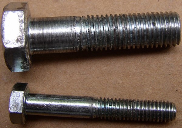
Sure enough, the 6mm outer aft bolt came out hard and had really messed up
threads. This kind of shoddy workmanship REALLY ticks me off. As
I was removing it, I could feel that it was tight, so I first removed the
fwd brace rod, to help relieve some of the tension on the mount bolts.
It appears that the SC bracket holes didn't line up well with the threaded
holes in the block, so the knucklehead who installed it just bulled and
jammed the bolts in there, damaging the threads against the bracket. I
also had to remove the RT header in order to get the SC mount bracket off,
as the bracket surrounds the header. After I got the bracket off, I
could see that the 6mm bolt had pretty messed up threads. Neither the
header nuts, nor the 2 10mm bolts holding the supercharger mount bracket on,
are using any sort of WASHERS. The bracket looks like it was put
on by the same "high school kid with a hammer and vise-grips" mentality that
my PSRU vent bottle was installed with. The PSRU vent bottle was not a
big issue, but someone messing with the threads in my BLOCK is a big deal.
1.5 hr
Here is a detailed picture of the items related to removing the
supercharger bracket, shown as the engine is mounted to the firewall, and
the order in which they are removed:
A = oxygen sensor (22mm or 7/8" wrench)
B = header nuts (17 mm socket)
C = fwd strut rod bolt 3/8" and 9/16" wrenches)
D = 10mm bolt for brace strut and supercharger frame (17mm head)
E = 10mm bolt for supercharger frame - this goes in at an angle
(17mm head)
F = 6mm bolt for supercharger frame (10mm head)
This pic shows the damaged threads on the bolts for the supercharger mount
bracket. Note also how much the shank of the 10mm bolt has ground
against the side of the mount bracket. Apparently the hole alignment
wasn't great, and the installer just jammed things in.
This shows the amount of aluminum chips that came from chasing the threads
in the 6mm hole for the SC mount bracket.
Aug 23 - more Eggenfellner STi Upgrade
chapter updates. Got my new heater with 1/2" fitting from Eggenfellner.
Put away yet another ACS order of various bolts & other misc hardware I've
had to stock up on to get the "complete FWF" finished. Prep new heater for
installation, and remove old heater cover plate. RTV the new heater
core inside the box, so it doesn't shift around in its box.
0.5 hr
Aug 24 - clean supercharger bracket mounting
hole threads, unpack & assemble magnehelic gage I received. I had
ordered the gage to help with analyzing cowl inlet & outlet sizes, as I will
probably follow recommendations and install a cowl flap.
0.5 hr
I
got this gage from a guy on ebay. Obviously, I didn't get the same
model Robert has installed in his plane. This thing is HUGE: about 5" in
diameter and weighs a couple pounds. I guess I won't have any
problem reading it. It's for measuring differential pressure
inside the cowl, to determine the best air inlet and outlet sizing.
Aug 25 - install heater, drill out header nuts
for safety wire, countersink fuel pumps frame, prep for installing mounting
nutplates on the fuel pumps mount frame. Drill fuel pumps for
nutplates. I can no longer stand handling the rough and sharp edges of
that red anodized fuel pumps frame, so I polished the edges.
4.0 hr + 2.0 hr doc
Here, I have drilled the header mount nuts for safety wire, using the jig at
the bottom of the pic. I marked which corners were the best 2 choices
when the nuts were installed and torqued. So, when I reinstall the
same nuts on the same studs, the safety wire holes should line up for proper
safety wiring.
This is the Eggenfellner fuel pumps frame, countersunk for flathead mount
screws so it will lie flat on the floor, and for nutplates for mounting to
the floor. It was supplied with round
head screws. I found that using a drill press to do the countersink
holes, with the countersink cage, worked very well, but it does seem to make
the countersinks deeper with the same cage setting than when using a hand
drill. The frame should have been made a tad bigger, so the holes
aren't quite so close to the edges. I'll next add nutplates for the
screws that will mount it to the floor (2 holes on each end).
Aug 26 - drill and countersink fuel pumps
frame for nutplates. Put fuel pumps assy into plane and ponder
placement. I should do the placement (for more accurate hole match
drilling) before I put those nutplates into the frame. That entails
deciding if I am going to retain the 2 throwaway pre-filters or go with Jim
Skala's idea of using low restriction fuel filter bags in the tank.
Jan is getting all the STi customers (about 20 of us) ready for the big
upgrade. I am doing the documentation on it for everyone. Thank
God I got the new flywheel and PRSU! Those look like a real big pain
to swap out. Also, Jan is now saying NOVEMBER to get the upgrade
parts. I'm still waiting to get my Andair fuel filter. I've been
pushing to get it, but actually I just realized that there's no rush on it,
because, like other firewall items, I need to get that supercharger and
intercooler installed, then install the rest of the stuff around them.
I went into town and got a couple of the in-tank fuel socks. Later, in
the evening, I made a couple bushings to mate the 3/8" fuel line to the
sock. The ID of the hole in the sock is 0.430, so I made the bushing
OD 0.434, for a good snug stretch fit into the plastic inlet, and I
reamed the ID to 0.374 for a good fit over the 3/8" fuel line. I
will later solder the bushing to the fuel line, using some aluminum solder I
got at OSH05.
2.75 hr + 1.0 hr doc
I am laying the pumps in there to see the best spot to mount them. I
may eliminate the pre-filters, to make the whole thing shorter, and just go
with in-tank fuel sock filters, as is done on the cars.
This is Jim Skala's fuel sock setup. See the Yahoo Eggenfellner group
Pictures section for more details & pics of how Jim did it.
Here
is one of the fuel socks I got. They go in the tank, at the end of the
fuel pickup. I got this idea from Jim Skala. If you go to the
parts store, they have a book with dozens of designs of these socks.
Many will work fine. This is a FS38. Jim used a FS140 with a
7/8" hole, so he made an adapter to go from the fuel line to the sock.
The guys at the parts store let me rummage through the boxes of socks they
had in stock (no FS140), and I thought this one would work just fine.
I will replace the Van's-supplied pickup with a tube that is completely open
at the end, with this sock well bonded onto the end of it.
Aug 27 - Planning layout for fuel pumps
assembly. Cleaned debris out of cabin. Finally decided on
pumps' location and drilled holes in cabin floor for that. Karla
helped dimple the holes. I installed the nutplates into the pumps
frame, assembled the fuel pumps assy, and installed the pumps into the
cabin. Then I worked on cleaning up the big mess on my workbench.
Things were on there several layers deep, and it was getting hard to
work there. 2.5 hr
The fuel pumps are finally mounted, after way too much screwing around.
I plan to use the pre-filters as added debris insurance prior to first
flight. I will probably remove the fuel filters when I am ready to fly
it. The socks in the fuel tanks will handle normal filtering - the
throwaway pre-filters are just in case some initial debris is in the lines.
This is how Carsten Schanche mounted his fuel pumps. Nice job, and he
didn't have to redo the red bracket to use flathead screws with it. I
probably should have done it that way. Part of my problem, though, was
that I needed to get the pumps as low as possible to clear the heater, which
couldn't go in any higher because of interference between the heater and the
firewall recess.
And this is how Carsten mounted his heater. Much higher than mine and
upside down from how I did it. He didn't fall for the "use the
firewall recess" like I did, and he used the flat replacement panel. You can also see his
ECM mounted on the RT side.
March 2, 2007 update - from the Eggenfellner list, here are
descriptions of how 2 other Eggenfellner customers mounted their fuel pumps:
Jerry Ballard: I have an elevated tray (1" above floor skin)
that my pumps are mounted in. The red bracket supporting the pumps are
mounted on vibration isolators on the tray. The tray is secured at the front
by the same bolts that secure the muffler bracket. The tray is supported at
the rear by 3/16" bolts with a 1" spacer that suspends the tray above 1/2"
foam insulation. The foam is on the floor. Between the tray and the foam are
the brake lines, battery cables, and fuel return line. The tray will collect
any spills or leaks and drain it overboard. I made a custom cover for the
tray, powder coated it, and lined it with 1/4 inch foam. Needless to say my
pumps cannot be installed to be any quieter.
See the Yahoo Eggenfellner group
Pictures section for more details & pics of how Jerry did it.
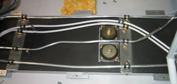
Here are 3 pics of Jerry's fuel pumps & muffler mounts installation:
muffler mounts, wires, fuel lines under fuel pumps mount tray
fuel pumps mount tray
with the cover in place
Allen Fulmer: I fabricated a bracket from short pieces of
3/4x3/4x1/8 angle and a piece of .063 sheet riveted between to mount red
bracket to. Then attached 2 nut plates per side on inside of angle so the
assembly could be attached with 4 bolts through floor angles. Plan on
putting a little scupper drain/vent under fuel valve ala Tom Moore's
installation.
Aug 28 - finish cleaning up the big mess on
the workbench 4.5 hr + 0.5 hr doc
Workbench all cleaned up again. I didn't have a square inch of clear
space on there to work, and tools and parts were several layers deep in
places. Wings (and dirtbike I'm replacing the carb on) in background.
Plane is off the pic to the left.
What to do next, while I wait for engine update parts? Let's
go back to the FUSELAGE
Aug 31 - one final Aug engine entry -
received my Gary Newsted Coolant Loss Sensor. It occurred to me
after I got it that I could have done the same thing cheaper by using one of the low
fuel level sensors for this application.
Gary Newsted's Coolant Loss Sensor system. The long white part goes in
the panel - on the LT is the indicator & "press to test". The mass of
nuts & bolts is the actual sensor that goes into the side of the tank.
 At
Oshkosh, I looked at Tom Moore's plane and saw what is supposed to be done
with the threaded hole at the top of the PSRU vent bottle. It needs a
plug with a tiny hole drilled in it. Jan didn't include
this plug with my PSRU vent bottle, so I ordered one from Wicks, and drilled
a #55 hole through it. Note I've also replaced the Eggenfellner-supplied,
too-short, PSRU vent bottle mount screws, added washers, and replaced the supplied nylon
locknuts with all-steel locknuts. See my
June page for the poor workmanship in
what Eggenfellner sent me.
At
Oshkosh, I looked at Tom Moore's plane and saw what is supposed to be done
with the threaded hole at the top of the PSRU vent bottle. It needs a
plug with a tiny hole drilled in it. Jan didn't include
this plug with my PSRU vent bottle, so I ordered one from Wicks, and drilled
a #55 hole through it. Note I've also replaced the Eggenfellner-supplied,
too-short, PSRU vent bottle mount screws, added washers, and replaced the supplied nylon
locknuts with all-steel locknuts. See my
June page for the poor workmanship in
what Eggenfellner sent me.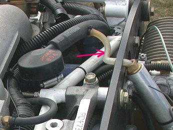
 I had been looking at my engine and thinking about how I can better support
a very floppy coolant tubing going to the LT radiator. This is how
Robert Paisley did his, and it looks like a fine way to do mine. I'll
have to order the parts, as the FWF didn't come with the parts to do this.
I had been looking at my engine and thinking about how I can better support
a very floppy coolant tubing going to the LT radiator. This is how
Robert Paisley did his, and it looks like a fine way to do mine. I'll
have to order the parts, as the FWF didn't come with the parts to do this.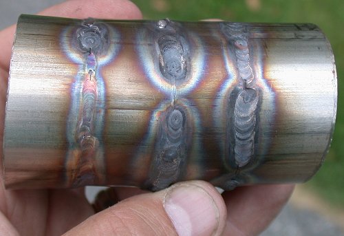 Practicing welding 0.050" stainless steel tubing from Burns. I started
at 50a, as on the RT, and ended up at 30a, as on the LT. Not too
great, but should be good enough to tack things in place for a pro to finish
the job. I'll be doing some more practice later. I'm also still
trying to decide exactly how I want to modify things to get the mufflers to
fit.
Practicing welding 0.050" stainless steel tubing from Burns. I started
at 50a, as on the RT, and ended up at 30a, as on the LT. Not too
great, but should be good enough to tack things in place for a pro to finish
the job. I'll be doing some more practice later. I'm also still
trying to decide exactly how I want to modify things to get the mufflers to
fit.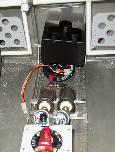 The fuel pumps assy had to be shoved way back to fit the heater in there.
I can't get the heater much higher because the firewall recess sticks
out. I suppose even if I'd put a flat panel in there, instead, I'd
still have interference with the F601E angle that goes across the bottom.
The fuel pumps assy had to be shoved way back to fit the heater in there.
I can't get the heater much higher because the firewall recess sticks
out. I suppose even if I'd put a flat panel in there, instead, I'd
still have interference with the F601E angle that goes across the bottom.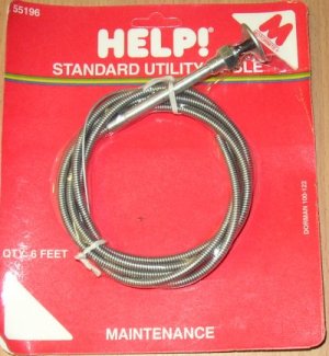 I've used these before, and they are not very reliable or long-lived.
No way am I putting this junk on my plane. I can't believe
Eggenfellner would use such poor quality parts on his FWF.
I've used these before, and they are not very reliable or long-lived.
No way am I putting this junk on my plane. I can't believe
Eggenfellner would use such poor quality parts on his FWF.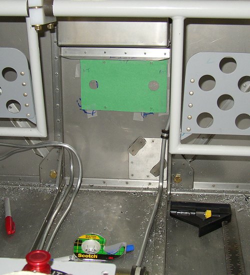 I made a cardboard pattern from the heater, and used that to lay out for
the heater. I wanted it as high as possible to get away from the
pumps, and as far to the RT as possible, to get away from the brake lines.
I bent a little jog in the fuel return line, just to the RT of the green
cardboard, so the heater will clear that. This looks like where I will
drill the firewall out. But, I want to check the heater installation
part of the Eggenfellner manual before I start cutting.
I made a cardboard pattern from the heater, and used that to lay out for
the heater. I wanted it as high as possible to get away from the
pumps, and as far to the RT as possible, to get away from the brake lines.
I bent a little jog in the fuel return line, just to the RT of the green
cardboard, so the heater will clear that. This looks like where I will
drill the firewall out. But, I want to check the heater installation
part of the Eggenfellner manual before I start cutting.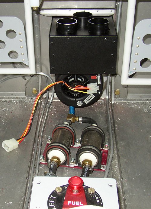 Here's the cabin view of the installed heater. The pumps are just
laying in there, and I will fit them in around the heater next. Man, I
gotta get all that debris vacuumed up in there! It's even worse out
the outer sides.
Here's the cabin view of the installed heater. The pumps are just
laying in there, and I will fit them in around the heater next. Man, I
gotta get all that debris vacuumed up in there! It's even worse out
the outer sides.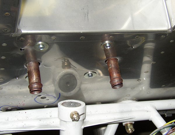 Here's the fwd firewall view of the installed heater. I don't dare put
the hoses on yet, though, because I am concerned about interference with the
intercooler. So, I still have to wait to install the intercooler
and supercharger before I can put anything else on the firewall. Also,
the heater kit apparently did not come with the tee fittings I will need to
tie these fittings into the heater hose lines.
Here's the fwd firewall view of the installed heater. I don't dare put
the hoses on yet, though, because I am concerned about interference with the
intercooler. So, I still have to wait to install the intercooler
and supercharger before I can put anything else on the firewall. Also,
the heater kit apparently did not come with the tee fittings I will need to
tie these fittings into the heater hose lines.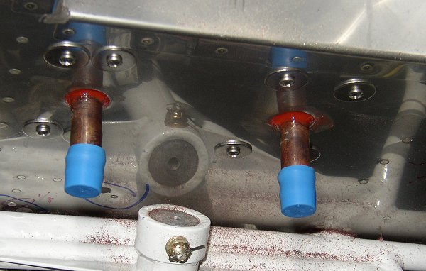 Here's the heater installed and the holes sealed with hi-temp silicone.
No sooner did I get this done than I realized I'd have to take it out again
to hammer the firewall recess in some more from a lower angle than I am able
to with the heater installed. The base of the firewall recess is "very
attractive" now.
Here's the heater installed and the holes sealed with hi-temp silicone.
No sooner did I get this done than I realized I'd have to take it out again
to hammer the firewall recess in some more from a lower angle than I am able
to with the heater installed. The base of the firewall recess is "very
attractive" now. This is a closeup of how the angles of the coolant reservoir and the
firewall do not mesh well. At the bottom is a 5/8" long bushing I made
on the lathe, to make the reservoir hang plumb. I ordered some of
Van's trailing edge wedge material to try to get something solid in there.
I also thought about putting a clay dam in there and filling it from the top
with epoxy & microballoons. We'll see how the wedge works out.
Others have made a big bracket to hold the reservoir, but I thought I could
do it simpler and lighter this way.
This is a closeup of how the angles of the coolant reservoir and the
firewall do not mesh well. At the bottom is a 5/8" long bushing I made
on the lathe, to make the reservoir hang plumb. I ordered some of
Van's trailing edge wedge material to try to get something solid in there.
I also thought about putting a clay dam in there and filling it from the top
with epoxy & microballoons. We'll see how the wedge works out.
Others have made a big bracket to hold the reservoir, but I thought I could
do it simpler and lighter this way.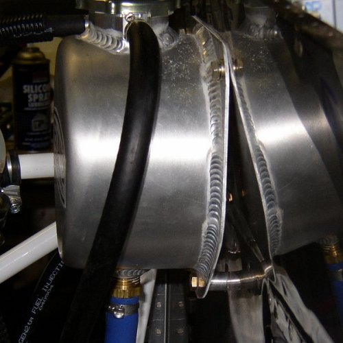 This pic shows the standoff spacer I made, so the coolant reservoir hangs
plumb.
This pic shows the standoff spacer I made, so the coolant reservoir hangs
plumb.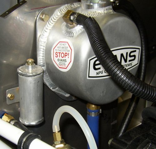 Here's the coolant reservoir installed as high and to the right as I could
get it, right up next to the brake fluid reservoir. I want to get it
as far as I can from the supercharger and I made the blue alignment line,
but then decided to get it a bit higher at the red line.
Here's the coolant reservoir installed as high and to the right as I could
get it, right up next to the brake fluid reservoir. I want to get it
as far as I can from the supercharger and I made the blue alignment line,
but then decided to get it a bit higher at the red line.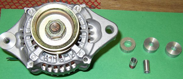 I made up 2 sets of bushings and spacers to enable a good fit for the
alternator mount system. The spacer on the LT is the one that was
installed. While the 1/2" hole didn't really hurt anything (on a
8mm stud), it sure was sloppy, and it was in serious need of some
deburring. It looked like they'd taken it directly from the
bandsaw and installed it on the engine. The 8-10mm adapter bushings go in the 10mm mount hole
at the base of the alternator, on the RT in this pic. I mailed the
second set of bushing and spacer to the STi builder who told me about
this mounting problem.
I made up 2 sets of bushings and spacers to enable a good fit for the
alternator mount system. The spacer on the LT is the one that was
installed. While the 1/2" hole didn't really hurt anything (on a
8mm stud), it sure was sloppy, and it was in serious need of some
deburring. It looked like they'd taken it directly from the
bandsaw and installed it on the engine. The 8-10mm adapter bushings go in the 10mm mount hole
at the base of the alternator, on the RT in this pic. I mailed the
second set of bushing and spacer to the STi builder who told me about
this mounting problem.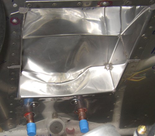 My, how attractive! I used the rivet gun, from the back, to hammer an
indentation in the back of the firewall recess, so I could get a flexible
duct onto the heater fwd outlet.
My, how attractive! I used the rivet gun, from the back, to hammer an
indentation in the back of the firewall recess, so I could get a flexible
duct onto the heater fwd outlet.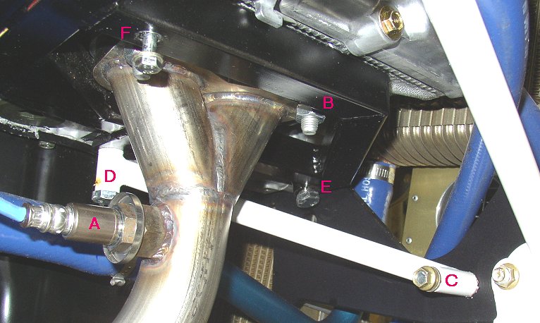
 This pic shows the damaged threads on the bolts for the supercharger mount
bracket. Note also how much the shank of the 10mm bolt has ground
against the side of the mount bracket. Apparently the hole alignment
wasn't great, and the installer just jammed things in.
This pic shows the damaged threads on the bolts for the supercharger mount
bracket. Note also how much the shank of the 10mm bolt has ground
against the side of the mount bracket. Apparently the hole alignment
wasn't great, and the installer just jammed things in.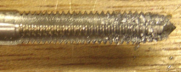 This shows the amount of aluminum chips that came from chasing the threads
in the 6mm hole for the SC mount bracket.
This shows the amount of aluminum chips that came from chasing the threads
in the 6mm hole for the SC mount bracket.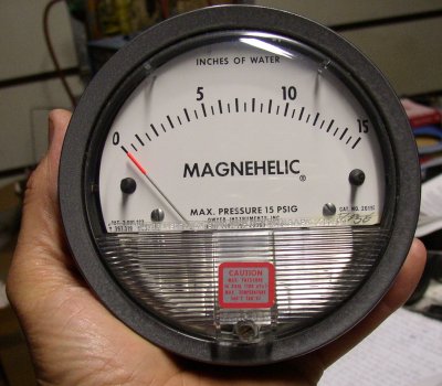 I
got this gage from a guy on ebay. Obviously, I didn't get the same
model Robert has installed in his plane. This thing is HUGE: about 5" in
diameter and weighs a couple pounds. I guess I won't have any
problem reading it. It's for measuring differential pressure
inside the cowl, to determine the best air inlet and outlet sizing.
I
got this gage from a guy on ebay. Obviously, I didn't get the same
model Robert has installed in his plane. This thing is HUGE: about 5" in
diameter and weighs a couple pounds. I guess I won't have any
problem reading it. It's for measuring differential pressure
inside the cowl, to determine the best air inlet and outlet sizing.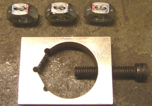 Here, I have drilled the header mount nuts for safety wire, using the jig at
the bottom of the pic. I marked which corners were the best 2 choices
when the nuts were installed and torqued. So, when I reinstall the
same nuts on the same studs, the safety wire holes should line up for proper
safety wiring.
Here, I have drilled the header mount nuts for safety wire, using the jig at
the bottom of the pic. I marked which corners were the best 2 choices
when the nuts were installed and torqued. So, when I reinstall the
same nuts on the same studs, the safety wire holes should line up for proper
safety wiring.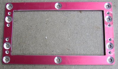 This is the Eggenfellner fuel pumps frame, countersunk for flathead mount
screws so it will lie flat on the floor, and for nutplates for mounting to
the floor. It was supplied with round
head screws. I found that using a drill press to do the countersink
holes, with the countersink cage, worked very well, but it does seem to make
the countersinks deeper with the same cage setting than when using a hand
drill. The frame should have been made a tad bigger, so the holes
aren't quite so close to the edges. I'll next add nutplates for the
screws that will mount it to the floor (2 holes on each end).
This is the Eggenfellner fuel pumps frame, countersunk for flathead mount
screws so it will lie flat on the floor, and for nutplates for mounting to
the floor. It was supplied with round
head screws. I found that using a drill press to do the countersink
holes, with the countersink cage, worked very well, but it does seem to make
the countersinks deeper with the same cage setting than when using a hand
drill. The frame should have been made a tad bigger, so the holes
aren't quite so close to the edges. I'll next add nutplates for the
screws that will mount it to the floor (2 holes on each end).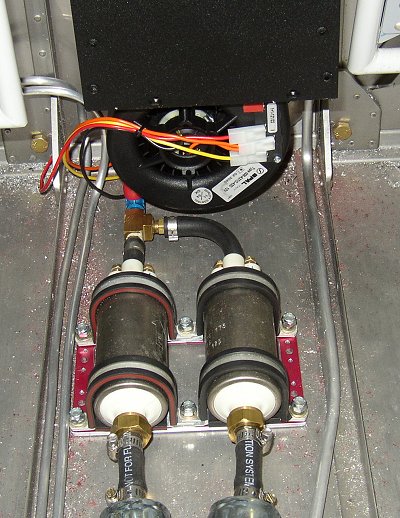 I am laying the pumps in there to see the best spot to mount them. I
may eliminate the pre-filters, to make the whole thing shorter, and just go
with in-tank fuel sock filters, as is done on the cars.
I am laying the pumps in there to see the best spot to mount them. I
may eliminate the pre-filters, to make the whole thing shorter, and just go
with in-tank fuel sock filters, as is done on the cars.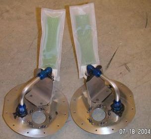 This is Jim Skala's fuel sock setup. See the Yahoo Eggenfellner group
Pictures section for more details & pics of how Jim did it.
This is Jim Skala's fuel sock setup. See the Yahoo Eggenfellner group
Pictures section for more details & pics of how Jim did it.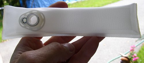 Here
is one of the fuel socks I got. They go in the tank, at the end of the
fuel pickup. I got this idea from Jim Skala. If you go to the
parts store, they have a book with dozens of designs of these socks.
Many will work fine. This is a FS38. Jim used a FS140 with a
7/8" hole, so he made an adapter to go from the fuel line to the sock.
The guys at the parts store let me rummage through the boxes of socks they
had in stock (no FS140), and I thought this one would work just fine.
I will replace the Van's-supplied pickup with a tube that is completely open
at the end, with this sock well bonded onto the end of it.
Here
is one of the fuel socks I got. They go in the tank, at the end of the
fuel pickup. I got this idea from Jim Skala. If you go to the
parts store, they have a book with dozens of designs of these socks.
Many will work fine. This is a FS38. Jim used a FS140 with a
7/8" hole, so he made an adapter to go from the fuel line to the sock.
The guys at the parts store let me rummage through the boxes of socks they
had in stock (no FS140), and I thought this one would work just fine.
I will replace the Van's-supplied pickup with a tube that is completely open
at the end, with this sock well bonded onto the end of it.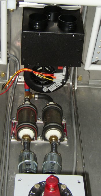 The fuel pumps are finally mounted, after way too much screwing around.
I plan to use the pre-filters as added debris insurance prior to first
flight. I will probably remove the fuel filters when I am ready to fly
it. The socks in the fuel tanks will handle normal filtering - the
throwaway pre-filters are just in case some initial debris is in the lines.
The fuel pumps are finally mounted, after way too much screwing around.
I plan to use the pre-filters as added debris insurance prior to first
flight. I will probably remove the fuel filters when I am ready to fly
it. The socks in the fuel tanks will handle normal filtering - the
throwaway pre-filters are just in case some initial debris is in the lines.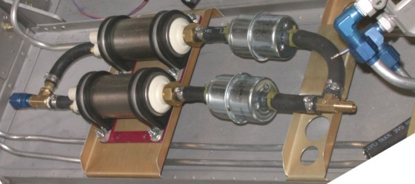 This is how Carsten Schanche mounted his fuel pumps. Nice job, and he
didn't have to redo the red bracket to use flathead screws with it. I
probably should have done it that way. Part of my problem, though, was
that I needed to get the pumps as low as possible to clear the heater, which
couldn't go in any higher because of interference between the heater and the
firewall recess.
This is how Carsten Schanche mounted his fuel pumps. Nice job, and he
didn't have to redo the red bracket to use flathead screws with it. I
probably should have done it that way. Part of my problem, though, was
that I needed to get the pumps as low as possible to clear the heater, which
couldn't go in any higher because of interference between the heater and the
firewall recess.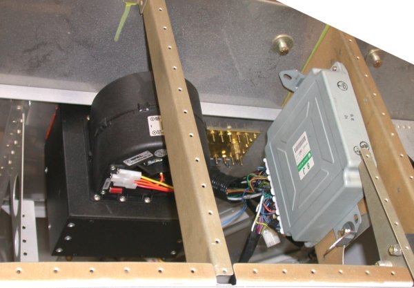 And this is how Carsten mounted his heater. Much higher than mine and
upside down from how I did it. He didn't fall for the "use the
firewall recess" like I did, and he used the flat replacement panel. You can also see his
And this is how Carsten mounted his heater. Much higher than mine and
upside down from how I did it. He didn't fall for the "use the
firewall recess" like I did, and he used the flat replacement panel. You can also see his
 muffler mounts, wires, fuel lines under fuel pumps mount tray
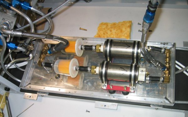 fuel pumps mount tray
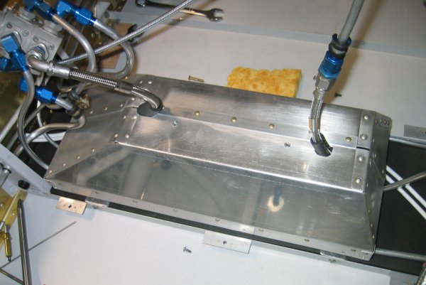 with the cover in place
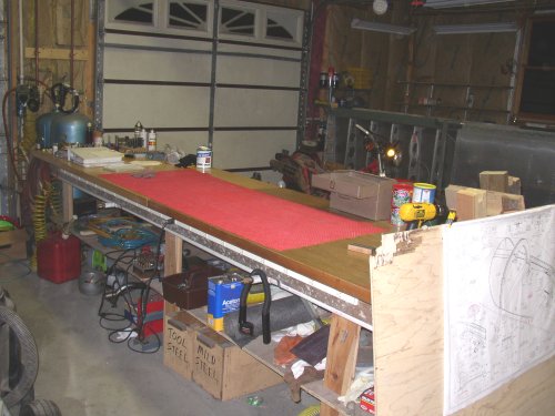 Workbench all cleaned up again. I didn't have a square inch of clear
space on there to work, and tools and parts were several layers deep in
places. Wings (and dirtbike I'm replacing the carb on) in background.
Plane is off the pic to the left.
Workbench all cleaned up again. I didn't have a square inch of clear
space on there to work, and tools and parts were several layers deep in
places. Wings (and dirtbike I'm replacing the carb on) in background.
Plane is off the pic to the left.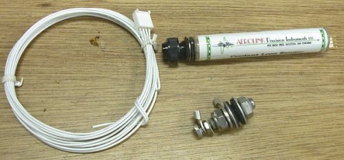 Gary Newsted's Coolant Loss Sensor system. The long white part goes in
the panel - on the LT is the indicator & "press to test". The mass of
nuts & bolts is the actual sensor that goes into the side of the tank.
Gary Newsted's Coolant Loss Sensor system. The long white part goes in
the panel - on the LT is the indicator & "press to test". The mass of
nuts & bolts is the actual sensor that goes into the side of the tank.