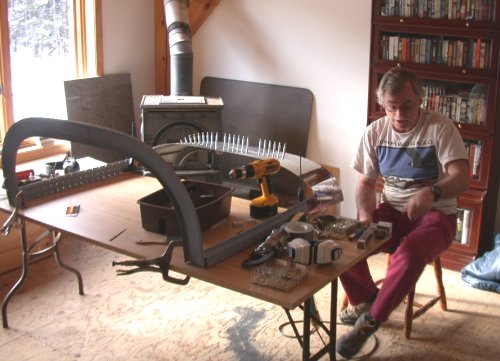
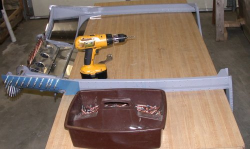 Here, I've dragged out a new table to work on, as my main workbench has too
much crap piled up all over it. I am drilling and clecoing the F7128A
center canopy frame brace into place.
Here, I've dragged out a new table to work on, as my main workbench has too
much crap piled up all over it. I am drilling and clecoing the F7128A
center canopy frame brace into place.CANOPY January, 2005
Jan 3 - Still working in Atlanta, so no plane work. Update web site 3.0 hr doc
Jan 4 - update web site 3.0 hr doc
Jan 10 update web site 1.0 hr doc
Jan 16 - Finally wrapped up the gig in Atlanta (actually, I quit early, largely because it was way too boring), and got back to the plane again. Spent some time trying to figure out where to get back into things. Decided I was overdue for installing the canopy frame optional reinforcement kit. The center piece fits OK, but the 2 side pieces don't even come close to fitting. Eventually, decided to use just the center brace and forget the 2 outer pieces. I also figured out that I need to completely finish the canopy frame and install & rivet the C702 fwd canopy skin before proceeding with installing the plexi bubble. Fit, drill, cleco center canopy frame brace F7128A. I also still don't know what to do with those C702 canopy skin aft ears that stick out & seem so out of place. I asked questions about the ears on the Yahoo RV7 list and got some good replies from Dan Checkoway and Len Loudis. They both just cut theirs off, although they each did it differently. Len sent me a large detailed picture of how he did his. He cut his off vertically at the slot, and made new, longer C603s. See Dan's site for how he did his, cutting horizontally aft from the bottom of the slot, similar to how I ended up doing mine. 3.0 hr
Here, I've dragged out a new table to work on, as my main workbench has too
much crap piled up all over it. I am drilling and clecoing the F7128A
center canopy frame brace into place.
Jan 17 - Drill C702 skin to tubing #30 holes. Final drill and cleco C702. Finally smartened up and moved this operation into the house. While working on the plane itself, I had to be out in the garage with the fuselage. Now that the canopy frame is completely riveted, the bubble is all trimmed to fit and drilled, and I am working on putting those pieces together, there's no point in trying to do it in the garage. In the house, the daylight is far better than in the garage, and it's about zero degrees out there, so it takes a lot of heat to warm it up, even to 60, plus using lots of electricity on the lighting. Brought canopy frame and related pieces & tools into the house. Then, worked on deburring the C702 and fabricated 3 shims of different thickness to slightly raise the fwd edge of the C702 skin, so it clears the aft edge of the F771 skin fwd of it when the canopy is raised. 2.5 hr
Jan 18 - more canopy frame and skin prep & fitting 0.5 hr
Jan 19 - set up the C-frame in the house and dimpled the C702 skin. Countersunk all the rivet holes in the canopy frame. Refitted frame to fuselage, to get a final check on fit and clearance between the C702 skin and the F771 skin fwd of it (I had thought the 0.025" shim made the C70s fwd edge not quite high enough, but the 0.032" shim made it a bit too high, so I went back to the 0.025" shim). Warmed the garage and bubble up enough to safely bring the bubble into the house, for later installation onto the frame. Also brought in some plexiglas scraps that I'd trimmed off the bubble, practiced my plexi drilling and countersinking, and set the countersink cage depth for the plexiglas work to come. 5.5 hr
 Here
I am using the C-frame (inside the nice warm house, right near the wood
stove, while it's about zero degrees out in the garage) to dimple the rivet
holes for the C702 canopy fwd skin. In this pic, I am dimpling the 10
or so holes that will not get any rivets, due to the gap between the skin
and frame. I am dimpling them, though, so the epoxy I will be using
will flow into the dimple holes and provide greater strength and a smoother
skin surface.
Here
I am using the C-frame (inside the nice warm house, right near the wood
stove, while it's about zero degrees out in the garage) to dimple the rivet
holes for the C702 canopy fwd skin. In this pic, I am dimpling the 10
or so holes that will not get any rivets, due to the gap between the skin
and frame. I am dimpling them, though, so the epoxy I will be using
will flow into the dimple holes and provide greater strength and a smoother
skin surface.
 One
more fitting of the C702 onto the cabin frame.
One
more fitting of the C702 onto the cabin frame.
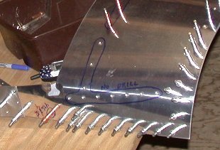 Here is a detail of the heavy blue line that outlines the 10 pre-punched
holes on each side of the C702, where there is a
gap between the skin and frame, so I
will be using epoxy there to fasten them together.
Here is a detail of the heavy blue line that outlines the 10 pre-punched
holes on each side of the C702, where there is a
gap between the skin and frame, so I
will be using epoxy there to fasten them together.
 I marked the C702 ears where I want to cut them off. This is a bit
different from how either Dan or Len did theirs, but I think this will work
well for me. The aft part of the cut will blend into the top fwd edge
of the C603.
I marked the C702 ears where I want to cut them off. This is a bit
different from how either Dan or Len did theirs, but I think this will work
well for me. The aft part of the cut will blend into the top fwd edge
of the C603.
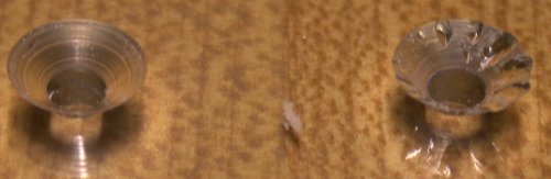 This
is a closeup of a couple of the test holes I drilled and countersunk, on a
piece of scrap canopy plexiglas. The one on the RT was with the
one-hole countersink cutter, and the one on the LT was with the 2-bladed
cutter. The one-hole cutter seems to leave a cleaner edge on metal,
but I think it cuts too aggressively for the plexi, causing lots of chatter
gouges. The one done with the other cutter did a nice job. I've
noticed that, with the one-hole c/s cutter, when countersinking aluminum, it
mostly produces a cutting scrap that is one piece of metal, about 1/8" wide
and an inch or so long, when it cuts the countersink. As I
showed much earlier, in countersinking
and deburring with the one-hole cutter, I get a much cleaner cut on metal,
but with plexi, you will want to use a countersink with multiple cutting
edges.
This
is a closeup of a couple of the test holes I drilled and countersunk, on a
piece of scrap canopy plexiglas. The one on the RT was with the
one-hole countersink cutter, and the one on the LT was with the 2-bladed
cutter. The one-hole cutter seems to leave a cleaner edge on metal,
but I think it cuts too aggressively for the plexi, causing lots of chatter
gouges. The one done with the other cutter did a nice job. I've
noticed that, with the one-hole c/s cutter, when countersinking aluminum, it
mostly produces a cutting scrap that is one piece of metal, about 1/8" wide
and an inch or so long, when it cuts the countersink. As I
showed much earlier, in countersinking
and deburring with the one-hole cutter, I get a much cleaner cut on metal,
but with plexi, you will want to use a countersink with multiple cutting
edges.
Jan 20 - final C702 skin trim & prep. Cut & trim C702 ears. Scuffed the skin and frame at the sides near the round hoop, where there is a gap between the skin and frame. I didn't drill the rivet holes there, because of the gap, and I will be filling the gap with epoxy, once the skin is riveted onto the frame. 2.0 hr
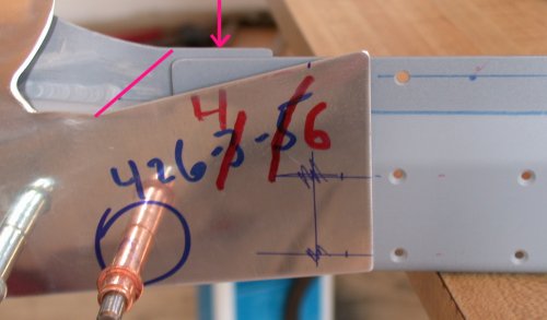
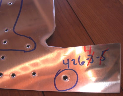 Here is what I ended up with after cutting off the tops of the ears.
Note that the fwd edge of the ear cutout is beveled with a file, so the
plexi bubble will lay there more smoothly. I still don't understand,
though, why there is no fastener used anywhere on the aft part of this tab.
I am quite tempted to add a fastener there. The aft-most hole goes
directly through one of the rivets holding the WD725, WD716, and C613 tie
plates together, so I drilled out that rivet and changed this hole to a
longer 1/8" rivet.
Here is what I ended up with after cutting off the tops of the ears.
Note that the fwd edge of the ear cutout is beveled with a file, so the
plexi bubble will lay there more smoothly. I still don't understand,
though, why there is no fastener used anywhere on the aft part of this tab.
I am quite tempted to add a fastener there. The aft-most hole goes
directly through one of the rivets holding the WD725, WD716, and C613 tie
plates together, so I drilled out that rivet and changed this hole to a
longer 1/8" rivet.
Jan 21 - Doing a gig in Cambridge, MA. Update web site 3.0 hr doc
Jan 22 - update web site 2.0 hr doc
Jan 23 - working around the clock from home for the gig in Cambridge, but I'm squeezing in a little time here & there on the plane. New England got a major snowstorm last night (32" north of Boston), so I also had to do a lot of shoveling & plowing today. Did final prep on C702 and canopy frame, then primed them and the C603, and clecoed them all together for riveting tomorrow. Since I'm working on this in the house now, Karla wouldn't appreciate it if I fire up the rivet gun at 0100. 1.5 hr + 1.0 hr doc
 Here is
the C702 and canopy frame, primed and ready to assemble. First, I
marked out on the C702 where the gaps would be between the C702 and the
canopy frame. Then I scuffed up both surfaces with 80 grit sandpaper,
to help the epoxy stick well. Then, I taped those areas off when I
primed, so I am epoxying bare metal. I will touch up the primer after
the riveting and epoxying are done. It's kinda tricky to do priming
when it's zero degrees out and I am working in a fairly airtight house.
I took each piece out to the garage, sprayed it quickly with primer, then
used a heat gun on it until the primer had flashed, then brought it back in
the house to cure awhile, before it could get too cold.
Here is
the C702 and canopy frame, primed and ready to assemble. First, I
marked out on the C702 where the gaps would be between the C702 and the
canopy frame. Then I scuffed up both surfaces with 80 grit sandpaper,
to help the epoxy stick well. Then, I taped those areas off when I
primed, so I am epoxying bare metal. I will touch up the primer after
the riveting and epoxying are done. It's kinda tricky to do priming
when it's zero degrees out and I am working in a fairly airtight house.
I took each piece out to the garage, sprayed it quickly with primer, then
used a heat gun on it until the primer had flashed, then brought it back in
the house to cure awhile, before it could get too cold.
Jan 24 - Talk about serendipity! I got an email this morning, after posting the above info from yesterday's work, from Matt Brandes. He warned me that I was about to rivet the C702 skin on without doing a couple important steps I'd missed. What a lucky break! Drawing 49 ISO view shows a couple rivets that are not pre-punched on the C702, on the aft part of that aft tab. I had previously wondered why there were no fasteners there, then I guess I just forgot about it. Anyway, Matt pointed out that I need to drill those 2 holes and countersink the frame there and dimple the skin for those 2 rivets. Not too easy to do after riveting the skin on! I also neglected to notice that I needed to take care of drilling, countersinking, and dimpling for the 2 screws on each side that hold the C725 canopy strut mount blocks in place. So, I fabricated those blocks. The plans said to fabricate them to 3/4" x 1/2" x 1 7/16"out of 1.5" x 3/4" aluminum block. The only aluminum block I had was the 1.25" x 5/8" blocks that were also for those little C723 wedges. I had the same issue back then, and Van's said then to just use the 1.25" x 5/8" blocks where it called for 1.5" x 3/4". I ended up not making the wedges anyway, so I had that material to use in making the C725 blocks. I cut them down to size using a coarse blade on the metal bandsaw, then I used the mill to smooth up the cut edge. Since it was 5/8" thick, and the plans called for making the blocks 1/2" thick, I milled 1/8" off the surface. I was wondering how the heck Van's thinks anyone else is going to do that, unless they happen to have a mill. I guessed they'd just have to leave them at 5/8" thick, or make a cobby mess filing or cutting 1/8" off the face. Anyway, as soon as I finished up all the mill work, I decided to look at the threaded ball joints that will get threaded into the C725 blocks. I couldn't find them in any of my hardware boxes. Then I said "hey, where are the struts?" I eventually found the struts in the package they came in. When I opened up the wrapping, lo and behold, not only was all the hardware taped inside, there was also a piece of 1/2" x 3/4" aluminum block, exactly the size needed to make the C725s without all the cutting and mill work. Grrrrrr. Due to doing computer work around the clock, all today's work was done in little quarter-hour and half-hour increments over another 18 hour day, whenever I could squeeze in a few extra minutes while scripts are running. It's FRIGID outside - about zero. It's SO much nicer to be working in the house. I cut the 2 C725 blocks to length, and laid out and drilled three #30 starter holes in each of them. 4.0 hr + 2.0 hr doc
So, three big lessons learned here. Heed and be happy:
1. Make sure you put in the 2 rivet holes that are NOT pre-punched, at the aft end of each C702 skin aft tab, BEFORE riveting the C702 skin.
2. Make sure you fabricate your C725 canopy strut mount blocks and drill & countersink the mounting holes in the C702 skin and cabin frame BEFORE you rivet the C702 canopy skin.
3. Don't let the plans fool you about what aluminum block stock to use to fabricate the C725 blocks - the strut package contains what you need to use, with a minimum of cutting; just cut to length and you're done.
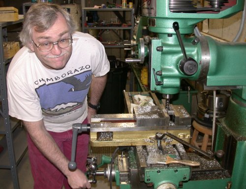
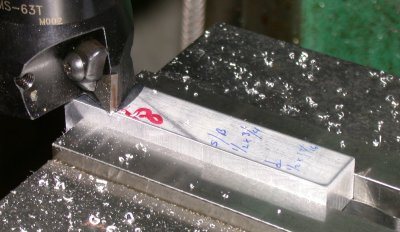 Milling the 1.25" x 5/8" bar stock down to 1/2" x 3/4".
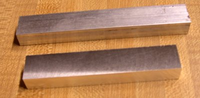 Foreground is the piece I milled from 1.25" x 5/8". Background is the
piece of 1/2" x 3/4" that came in the strut package. Oh well, using
the mill was fun.
Foreground is the piece I milled from 1.25" x 5/8". Background is the
piece of 1/2" x 3/4" that came in the strut package. Oh well, using
the mill was fun.
I cut the blocks to length, located and drilled three #30 starter holes in each. Then I started to mark on the frame where they need to be installed. I didn't continue work on the blocks, because I found they didn't go on quite as pictured in the drawing. Instead, I wrote to Van's about it. So tomorrow, I'll see what they say about that. This was the question I posed:
DWG 49 for 7A tipup says the block should be 3/8” fwd of the fwd edge of the C613 canopy frame splice plate. The ISO drawing on DWG 49 shows the screw holes for the C725 centered between the 2 rivets (see attached pic #1). Attached pic #2 shows the blue line laid out 3/8” fwd of the fwd edge of the C613 splice plate. As you can see in the pic, the rivet closest to the C613 will be UNDER the C715 block. I can handle this with a counterbore, but the 2 screws will not be centered between the 2 rivets, as shown in the drawing. So, should I stick with the specified 3/8” and counterbore the outside of the C725 block to clear the rivet shop head, or should I center the block between the 2 rivets, and adjust the location of the aft strut mounting accordingly for the proper end-to-end length of the strut?
 This pic from DWG 49 shows where the 2 mystery rivets go, and it shows where
the 2 screws go for holding on the C725 block. The screw holes look
centered between the 2 rivets.
This pic from DWG 49 shows where the 2 mystery rivets go, and it shows where
the 2 screws go for holding on the C725 block. The screw holes look
centered between the 2 rivets.
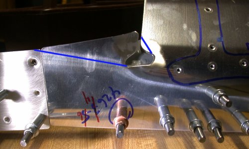
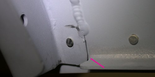
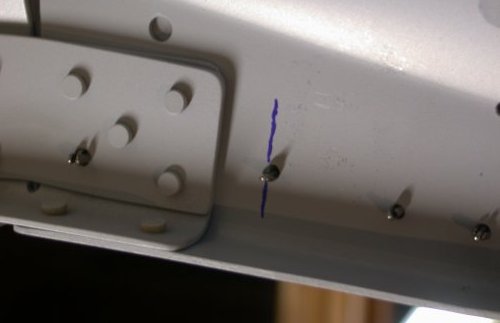 This pic shows the inside of the LT canopy frame, with the blue line showing
the specified 3/8" fwd of the C613 splice plates. As you can see,
putting it here will be over the rivet, so I will have to rivet first, then
counterbore the outside of the C725 block to make it fit here. Or, I
can just move it fwd a bit and center it between the 2 rivets. You can
also see here where I had to drill out one of the 1/8"
rivets holding the splice plate together, because that rivet needs to also
go through the skin. You can also see how I
did the C613 splice plate, instead of how
the plans specified.
This pic shows the inside of the LT canopy frame, with the blue line showing
the specified 3/8" fwd of the C613 splice plates. As you can see,
putting it here will be over the rivet, so I will have to rivet first, then
counterbore the outside of the C725 block to make it fit here. Or, I
can just move it fwd a bit and center it between the 2 rivets. You can
also see here where I had to drill out one of the 1/8"
rivets holding the splice plate together, because that rivet needs to also
go through the skin. You can also see how I
did the C613 splice plate, instead of how
the plans specified.
 The plans don't say anything about where to locate those 2 rivets that the
C702 is not pre-punched for, but it's obvious that they need to be centered
between the aft edge of the C613 and the aft edge of the C702 skin tab.
You can also see here where I had to drill out one of those 1/8" rivets in
the splice plate, to allow the rivet in the skin to go through there,
although the skin rivet hole and dimple had to be changed to 1/8" to accommodate this.
The plans don't say anything about where to locate those 2 rivets that the
C702 is not pre-punched for, but it's obvious that they need to be centered
between the aft edge of the C613 and the aft edge of the C702 skin tab.
You can also see here where I had to drill out one of those 1/8" rivets in
the splice plate, to allow the rivet in the skin to go through there,
although the skin rivet hole and dimple had to be changed to 1/8" to accommodate this.
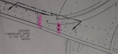
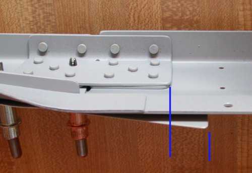
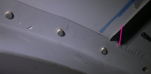
 The 2 rivets (for each side) also should be placed so they are in line with
the rivets holding the C603 to the canopy frame; hence, this is where I will
drill for them. I still think there should be one more screw going
through the skin, canopy bubble, and canopy frame, right below where the
arrow is, in the center of the overlap between the WD725 and WD716 canopy
frame weldment tabs. But, as is obvious, I already
trimmed the skin differently, so now it's impossible to do. I
didn't think of this until I had already trimmed the C702 skin tab back.
If I had it to do again, that ear or tab at the aft part of the C702 canopy
skin should have been trimmed as shown in the pink line. Then I could
have added one more screw under the arrow. Oh well; not a big deal - I
guess this is how everyone builds them, but I still don't understand why the
plans don't call for
one more screw at the fwd end of the line of screws.
The 2 rivets (for each side) also should be placed so they are in line with
the rivets holding the C603 to the canopy frame; hence, this is where I will
drill for them. I still think there should be one more screw going
through the skin, canopy bubble, and canopy frame, right below where the
arrow is, in the center of the overlap between the WD725 and WD716 canopy
frame weldment tabs. But, as is obvious, I already
trimmed the skin differently, so now it's impossible to do. I
didn't think of this until I had already trimmed the C702 skin tab back.
If I had it to do again, that ear or tab at the aft part of the C702 canopy
skin should have been trimmed as shown in the pink line. Then I could
have added one more screw under the arrow. Oh well; not a big deal - I
guess this is how everyone builds them, but I still don't understand why the
plans don't call for
one more screw at the fwd end of the line of screws.
Jan 25 - Gus at Van's got back to me with this answer on the C725 blocks:
Either solution would work. The position of the mounting block is not critical. Just make sure if you do move it forward that the strut will not hit the canopy deck F-721A
I was up to my neck in computer support work all day and night, but managed to squeeze in a few half-hours here and there. I match drilled the C725 blocks to the frame & skin, centering them between the 2 existing rivets. Then I drilled and reamed the block holes to size and tapped them, using my handy little tapping machine. 1.75 + 0.5 doc
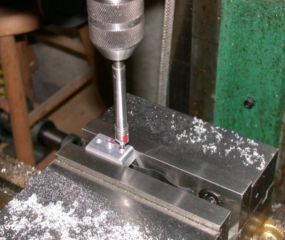
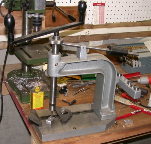 I
used my tapping machine to do the tapping on the C725 block. It works
great on small things that will lie flat. It ensures that the tap is
perfectly perpendicular to the work piece. It also holds the piece in
place, but lets it move laterally a bit so the hole gets perfectly centered
under the tap. You could use a drill press for this, but it takes 3
hands to do it, and it's a lot less convenient turning the spindle by hand.
I
used my tapping machine to do the tapping on the C725 block. It works
great on small things that will lie flat. It ensures that the tap is
perfectly perpendicular to the work piece. It also holds the piece in
place, but lets it move laterally a bit so the hole gets perfectly centered
under the tap. You could use a drill press for this, but it takes 3
hands to do it, and it's a lot less convenient turning the spindle by hand.
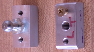 Here
are the completed C725 canopy frame strut mount blocks. You'll need to
radius the lower outer corner of each, so they fit the C725 weldment flange snugly.
Here
are the completed C725 canopy frame strut mount blocks. You'll need to
radius the lower outer corner of each, so they fit the C725 weldment flange snugly.
Jan 26 - Drilled out the skin and frame for the #10 screws for the canopy strut blocks. Dimpled the skin and countersunk the frame for all 8 new holes. Countersinking the thin frame for the #10 screws enlarged the holes quite a bit, but I had no choice, to get the skin dimples to sit in them. I realized that, because the effective depth of the #10 countersinking was deeper than the thickness of the frame, I'd have to countersink the blocks a bit, too. I used a #8 countersink cutter (#10 pilot wouldn't fit into the threaded #10 screw holes) in my mill, and just cut a little way into the blocks, to the depth that the overall countersink needed to be to seat the dimple in the skin. Touched up the primer on the skin and frame. Clecoed the skin on and got my riveting tools out of the garage. It's so bitter cold out (high of about 5 degrees all week) that it hurt my bare hands just to carry those frozen tools into the house. Did I mention how nice it is to be working in the house, in front of the big windows and right beside the wood stove? I didn't do any riveting yet, because I wanted those frozen tools to get a bit warmer first. 2.25 hr
I don't follow every email on the RV7 Yahoo list (too many "which rivet gun should I get", "how should I prime" questions, and questions that were just discussed the week before), but I occasionally look there to see what's going on. Roberta Hegy (who got her plane flying awhile ago) reported a new Service Bulletin from Van's for R-7 and R9 people with tipup canopies. HERE is a link to the SB. I'm sure glad I happened to catch that message! Apparently, it's a revision and strengthening of how the aft end of the F632A channel attaches to the F706A bulkhead. So, I guess I'll be revisiting that part of building the FUSELAGE.
 Here, I am adding a partial countersink to the C725 blocks, using the mill.
I only wanted to countersink the amount that the frame was too think to
accept, so the dimpled skin would sit nicely into the countersink.
Once I established how deep to do it, then I just brought the table up to
that point for each screw hole. Quick & easy.
Here, I am adding a partial countersink to the C725 blocks, using the mill.
I only wanted to countersink the amount that the frame was too think to
accept, so the dimpled skin would sit nicely into the countersink.
Once I established how deep to do it, then I just brought the table up to
that point for each screw hole. Quick & easy.
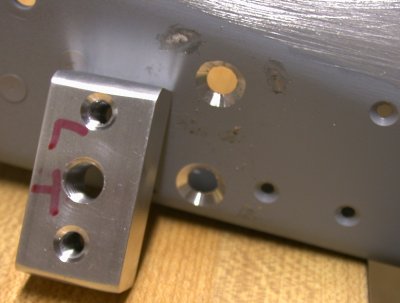 Here is the completed and partially countersunk C725 block and the
countersunk holes in the frame for the skin dimples. You can see the
upper hole in the frame had some chatter on the top. Once the depth of
the countersink exceeds the thickness of the metal being cut, you have to
hold the base of the countersink cage very tightly to the metal, so it
doesn't more around.
Here is the completed and partially countersunk C725 block and the
countersunk holes in the frame for the skin dimples. You can see the
upper hole in the frame had some chatter on the top. Once the depth of
the countersink exceeds the thickness of the metal being cut, you have to
hold the base of the countersink cage very tightly to the metal, so it
doesn't more around.
Jan 27 - Started riveting the skin onto the canopy frame. Started with the easy stuff; the pop rivets. I decided to use LP4-3 universal head pop rivets instead of CS4-4 flush pop rivets. It didn't seem to make whole lot of difference to me, and I thought that countersinking the holes in the round tubing, to accommodate flush rivet dimples in the skin, might enlarge the holes and cause the pop rivets to have a hard time holding. Then I squeezed all the rivets that could be squeezed (along the sides). Worked until 0400 on it, between computer work. Back up at 11 and continue computer work all day & evening, and plane work in little quarter- or half-hour increments. In the daylight, and after some rest, I could see that some of the rivets I squeezed last night were rather marginal. I probably should have used -4.5 instead of -4 in a couple places. Some of the shop heads are a bit small, and the rivet should have been squeezed more due to some hole enlarging that occurred when initially getting the skin to fit the frame. I did re-squeeze a few of the rivets 1/4 turn more on the squeezer. Then I started the part I dread; driving rivets. I worked on a few off and on all day, proceeding very slowly. Most were OK, I guess. A couple had to be redone. It was very difficult to do the rivets on the curved corners by myself. The guns wants to walk when it's on a convex surface. A couple rivet holes I didn't try yet look extremely difficult, because of flanges in the way. After Karla came home, she helped me riveting some of the tougher ones. It was quite frustrating. Karla was doing OK on the gun, but I just couldn't get the *&^%$#* shop heads to come up right. The rivets kept bending over, even though I was sure I had the buck square. We did get one difficult rivet in OK, but most of the others had to be redone over and over, and they still suck. If I wasn't already committed to the 3/32" dimples and countersunk holes in the frame, I'd say to hell with it, pay the $1+ each, and use Cherrymax rivets, as I had to do back when I was struggling with the aft fuselage bulkhead. I sent an email to another RV builder in NH to see if he can help me with the riveting. One, these jobs I have the problems with are tough, and second, with a Quick Build, I really haven't had to do a lot of rivet driving, so I don't think I am very good at it. Actually, after reviewing the pictures I took of the 2 worst rivets (they look worse in person than in the pic), I think tomorrow I will drill them out to 1/8" and try them again with "oops" rivets. Maybe one reason they bend over so easily is because they're wobbly in the enlarged hole. Maybe a 1/8" shank will also be less likely to bend. 4.75 hr + 2.5 doc
 I
had to make this custom bucking bar to to get at the 2 worst rivets to do
(on each side); the one in the middle of the curve, hidden behind flanges in
2 directions, and at the lower fwd corner.
I
had to make this custom bucking bar to to get at the 2 worst rivets to do
(on each side); the one in the middle of the curve, hidden behind flanges in
2 directions, and at the lower fwd corner.
 This shows the rivets in the middle of the curve at the fwd edge of the
skin. The rivet you see on the RT is the real bitch. It's bent worse than it
looks in the pic. It's been drilled out and retried about 5 times.
I had to make a special buck just to get in there, between the flange in the
upper RT and the flange along the bottom. The one to the left of it
looks like it just needs some more driving, but it's pretty marginal, too.
The gouge marks (as well as the rivet bending) indicate to me that I must
not be holding the buck square, but it sure seems while I am doing it that I
am. Very frustrating. This is on the RT side. We were able
to get this one on the LT side OK on the first attempt.
If you're reading this before you get this far in
building your own, I'd strongly suggest grinding off the corner of that
flange, as indicated by the pink line. It'll make life easier for you when you go to
rivet this thing together.
This shows the rivets in the middle of the curve at the fwd edge of the
skin. The rivet you see on the RT is the real bitch. It's bent worse than it
looks in the pic. It's been drilled out and retried about 5 times.
I had to make a special buck just to get in there, between the flange in the
upper RT and the flange along the bottom. The one to the left of it
looks like it just needs some more driving, but it's pretty marginal, too.
The gouge marks (as well as the rivet bending) indicate to me that I must
not be holding the buck square, but it sure seems while I am doing it that I
am. Very frustrating. This is on the RT side. We were able
to get this one on the LT side OK on the first attempt.
If you're reading this before you get this far in
building your own, I'd strongly suggest grinding off the corner of that
flange, as indicated by the pink line. It'll make life easier for you when you go to
rivet this thing together.
 In the center of this pic is the rivet for the lower fwd corner. It's
a bitch to get to, although not as bad as the one in the middle of the
curve. This rivet is useless, and will have to be drilled out.
The hole is oversize, too. After seeing these pics and writing up this
description, I think I'm going to drill these problem/oversize holes out to
1/8", and use "oops" rivets. I'd recommend cutting the corner of this
flange off, too.
In the center of this pic is the rivet for the lower fwd corner. It's
a bitch to get to, although not as bad as the one in the middle of the
curve. This rivet is useless, and will have to be drilled out.
The hole is oversize, too. After seeing these pics and writing up this
description, I think I'm going to drill these problem/oversize holes out to
1/8", and use "oops" rivets. I'd recommend cutting the corner of this
flange off, too.
Jan 29 - get out "oops" rivets (1/8" shank, 3/32" head), drill out bad rivets, and drill #30 for oops rivets. Exchanged emails with Phil Cobbin about him coming by to help me get this damn canopy frame C702 skin riveted on. Phil is building a tipup slow build RV-7 in his garage (summer) and house (winter) in Enfield, about 30 miles away. He's built his fuselage and both wings, so he has a lot more experience driving rivets than I do. 0.5 hr
Jan 30 - Phil stopped by to help put this C702 skin riveting to bed. The first thing he said was that the bucking bar I made was not cutting the mustard. It's too light and, because of the offset handle, it makes it very difficult to hold the bucking force in line with the rivet and gun. He had a bucking bar that was about 1" x 1" x 6" stainless square bar stock. The end was already notched (to clear the flange coming in from the side). We took it downstairs to the mill and milled out another notch in the middle of it, to clear that fwd flange on the WD716 weldment. This way, the bucking bar, and the force behind it, are in a straight line in line with the rivet and the gun. That worked MUCH better, although even Phil had a hell of a time preventing some of the rivets from bending over. They seem to have a huge proclivity to bend fwd, toward the flange. Even with Phil tipping the bucking bar at an exaggerated angle fwd, the damn rivets kept wanting to bend fwd. The ones near the hinges are also quite hidden, and very difficult to get to. We redid several, changed some to "oops" rivets, and eventually got them all "good enough". Definitely not great or perfect, but just good enough. What a bitch of a job! We worked on them for a couple hours or more, as well as the couple hours or more that I worked on them alone and the couple hours that Karla and I worked on them together. After Phil left, I set up to back rivet the canopy frame brace in place. As I did once when building the tail, I got so wrapped up in setting it up that I did a great job of doing about a dozen back rivets, then realized I FORGOT to put the brace piece in place before riveting. Duh! Well, it's pretty easy to drill out rivets that are only going through one piece of metal. Back riveted the canopy frame brace in place. Then, I stood the frame on end to prep it for epoxying the gaps between the skin and frame. I spent too much time adding lots of microballoons to the first batch of epoxy, stirring for a long time, so it started getting too stiff too soon; after I'd done one side, but before I'd done the other side. On the second batch, I went too far the other way; I should have used more microballoons and stirred longer. That batch worked OK, but it was too thin and took too long to cure. It was so thin for so long, it was seeping out under the rather hastily-applied duct tape. I was kept quite busy wiping up the excess, and adding more to the top, as it stiffened way too slowly. It finally set up enough to pull the duct tape off without disturbing the epoxy. Then, while the epoxy was in a plastic state, I used an X-Acto knife and a razor blade to trim off as much excess as I could. Then it was time to go to off the airport to do a new gig in MI. God, I hate commercial air travel, especially after 9/11 and our new Totally Screwing Aviation department. It sure will be nice when this plane is done and I can fly myself to jobs. 8.5 hr
 Here's Phil looking over the project he came to help with. The frame
is clamped to the table at 4 corners, so it isn't sliding all over the
place.
Here's Phil looking over the project he came to help with. The frame
is clamped to the table at 4 corners, so it isn't sliding all over the
place.
 Here's Phil milling out a slot in the new bucking bar.
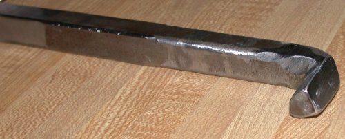
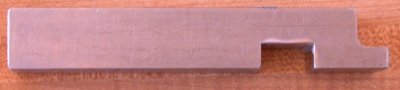 This is the shape of the bucking bar you need to drive those recalcitrant
rivets, especially the ones in the middle of the curve - the ones hidden by
2 flanges. It's about 1" square and 6" long. The end cutout gets
by the flange on the side, and the middle cutout avoids the lower flange on
the fwd channel of the WD716 weldment, as shown in the first "cut off the
corner of this flange" pic above. The slot is about an inch wide.
With a nice straight bucking bar like this, the force and the mass are all
directly in line with the rivet and the gun force vector. If you don't
have a mill, you can do this notching with a bench grinder, a grinding or
cutoff wheel in your die grinder or cutoff tool, or even a bandsaw.
This is the shape of the bucking bar you need to drive those recalcitrant
rivets, especially the ones in the middle of the curve - the ones hidden by
2 flanges. It's about 1" square and 6" long. The end cutout gets
by the flange on the side, and the middle cutout avoids the lower flange on
the fwd channel of the WD716 weldment, as shown in the first "cut off the
corner of this flange" pic above. The slot is about an inch wide.
With a nice straight bucking bar like this, the force and the mass are all
directly in line with the rivet and the gun force vector. If you don't
have a mill, you can do this notching with a bench grinder, a grinding or
cutoff wheel in your die grinder or cutoff tool, or even a bandsaw.
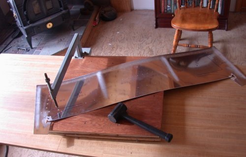
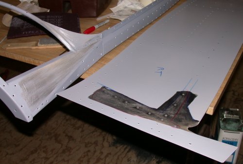
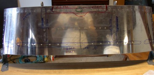 Here
is the canopy frame and completely riveted C702 skin. It is standing
with the C631A end on the floor, and held in place to the edge of the table by duct
tape, in preparation for filling the vertical skin-frame gaps with epoxy. You
can see all the notes all over the top of the skin. For the FAA, you
can also see me in the skin reflection, taking the pic. I got the West
System epoxy and pumps from
Soller Paddles, the cheapest prices I found, plus they're located right
here in NH.
Here
is the canopy frame and completely riveted C702 skin. It is standing
with the C631A end on the floor, and held in place to the edge of the table by duct
tape, in preparation for filling the vertical skin-frame gaps with epoxy. You
can see all the notes all over the top of the skin. For the FAA, you
can also see me in the skin reflection, taking the pic. I got the West
System epoxy and pumps from
Soller Paddles, the cheapest prices I found, plus they're located right
here in NH.
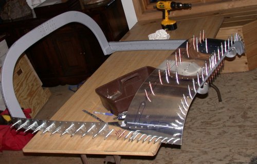
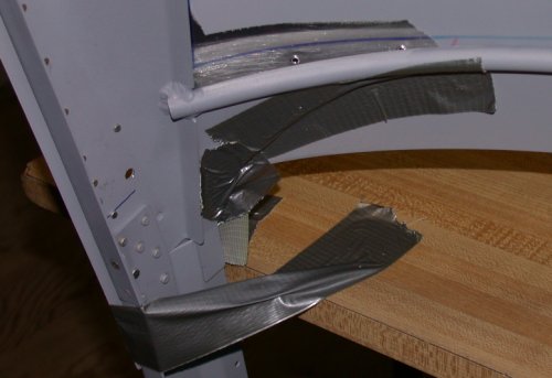 Here is the inside view of the canopy frame, ready to epoxy the vertical gaps between
the skin and frame. The frame is standing vertically on its C631A end. This has to be done in 2 steps - first
the vertical holes under the
tubing loop, then later the horizontal holes under the side skin, while the frame is sitting at
its normal angle. The duct tape on the table holds the frame in place.
The duct tape on the frame holds the epoxy in at the bottom, while the epoxy
is put in from the top. The skin and frame have been roughened with
#80 sandpaper to give the epoxy something to grip to.
Here is the inside view of the canopy frame, ready to epoxy the vertical gaps between
the skin and frame. The frame is standing vertically on its C631A end. This has to be done in 2 steps - first
the vertical holes under the
tubing loop, then later the horizontal holes under the side skin, while the frame is sitting at
its normal angle. The duct tape on the table holds the frame in place.
The duct tape on the frame holds the epoxy in at the bottom, while the epoxy
is put in from the top. The skin and frame have been roughened with
#80 sandpaper to give the epoxy something to grip to.
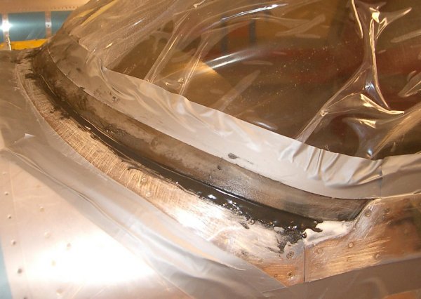
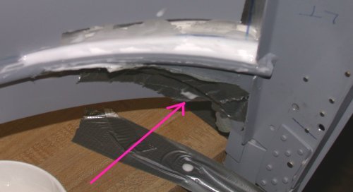 Here is the LT side vertical gap filled with epoxy. This is the side I did second, with epoxy
I should have made thicker and stirred longer. It was so thin, the
epoxy was seeping out under the duct tape, front and back, as well as running over the top,
due to the top not being perfectly level. The arrow shows one place
the epoxy was leaking out. I didn't have these problems on the RT side
I did first, but OTOH that side stiffened up on me before I was ready for
it. When it was cured to a plastic state, I was able to clean it all
up OK. TIP = make sure the epoxy you use has enough microballoons
to be just thin enough to flow down into the gap, but no thinner than
necessary.
Here is the LT side vertical gap filled with epoxy. This is the side I did second, with epoxy
I should have made thicker and stirred longer. It was so thin, the
epoxy was seeping out under the duct tape, front and back, as well as running over the top,
due to the top not being perfectly level. The arrow shows one place
the epoxy was leaking out. I didn't have these problems on the RT side
I did first, but OTOH that side stiffened up on me before I was ready for
it. When it was cured to a plastic state, I was able to clean it all
up OK. TIP = make sure the epoxy you use has enough microballoons
to be just thin enough to flow down into the gap, but no thinner than
necessary.
Here are some pics Phil took during his visit:
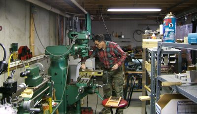 Milling the
bucking bar in the basement
Milling the
bucking bar in the basement
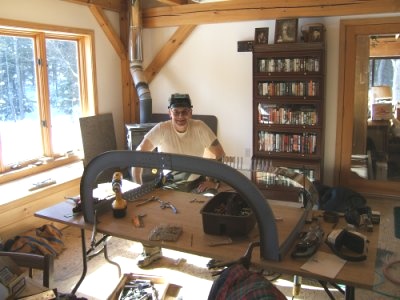 Working on
the frame & skin in the dining room. It sure is nice, working right
beside the windows and the wood stove.
Working on
the frame & skin in the dining room. It sure is nice, working right
beside the windows and the wood stove.
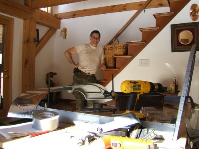 Another
shot from inside the "winter workshop".
Another
shot from inside the "winter workshop".
Jan 31 - update web site 2.5 hr doc
GO TO FEBRUARY CANOPY
BACK TO MY RV BUILDER'S HOME
BACK TO BRIAN'S HOME