May 1 - Back to studying Drawings
18, 20, 25, and 40 to figure out how the F-631C brackets mount, so I can
measure the fuselage width at that point, and get on with making the cabin
frame. After removing the F-757T and F-705G that were pop riveted into
place with the F-721B deck, F-718 longeron, and F-705F, I was able to figure
out that the F-721B had been permanently riveted into the QB kit as a SLIDER
configuration, not my TIPUP configuration, and that I'd need to make some
more cuts, in place, on the F-721B, including a very dangerous cut right
over the longeron. The F-757T also needed a square hole cut in it for
a tipup canopy. So, I made the cuts, VERY carefully. I used a
piece of scrap aluminum between the F-721B and the F-718. One slip
cutting into that longeron, even a little bit, and I'd be screwed. As
I believe the square hole on the F-757T is just for finger access, same as
the holes on the aft F-631A pieces, I did it much more easily with a holesaw,
rather than screwing around making a square hole.
I later found out this is not a finger access hole,
but where the canopy latch lug goes through. So, round was not a big
problem, but it's best to cut the square hole as per the plans.
Then I had to do
lots of filing and deburring, in the cramped space around the F-721B, to get
everything nice and smooth. I finally thought I had it about figured
out as to how the F-631C and D angles would go in, with the interfering
portions of the F-721B now cut away, so I repeated the process on the RT
side. A key piece of information was that I finally realized the
F-631C goes OUTside the 631s and the F-631D angle goes INside them, so the
F-631C and D angles now went together in a logical and feasible way
(otherwise the holes in the C would not both hit the D). It finally
started looking like it made sense and matched the drawings, so I got my
measurement at 42 1/8", not the nominal 42 5/32". So, it was
only a 1/32" difference from the plans, anyway. I got a piece of
plywood (from a Van's crate) and clamped it to my table, so I could drill
and cleco the F631As in place, once I had them clamped down right where I
wanted them. Laid out and drilled aft F-631As and F-631E
plate. 8.0 hr
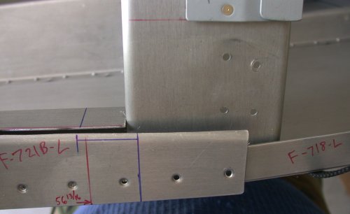
After
I labeled each part that came in the QB kit, and studied the plans
extensively, I figured out that at least part of the reason I couldn't
figure out how the F-631C angle went in was because the F-721B was
interfering with it, because it had been trimmed at the factory for a slider
canopy, not for my tipup. The blue lines indicate where the cuts have
to be made for a tipup canopy configuration. Forward of this picture,
all the F-721B holes are permanently riveted, so this has to be trimmed in
place. The F-757T and F-705G were installed with temporary pop rivets
in the QB kit, and have been removed in this pic. The mark I made here
for fuselage station 56 13/16 turned out to be incorrect, so ignore
that. FS 56 13/16 turns out to be right where that blue line cuts
across the F-721B, over the inside edge of the F-705F.
This
is the F757T from the LT side, after drilling out the temporary pop
rivets. The plans called for a square hole in this (for a tipup), but
I assumed it was just for an access hole, like on the aft F-631As, so I just
used a hole saw; much quicker and easier. NOTE: I Later found
out it should have been a square hole. It doesn't affect anything but
appearance, but it isn't right. The tipup canopy frame latching
fingers go through the hole.
Here
is a somewhat fuzzy pic of me making these dangerous cuts to the
F-721B. One slip of the cutter, and I am DOOMED, especially when
making that cut right over the upper longeron. I slipped a piece of
scrap in between the 2 pieces, to protect the longeron.
Here
is what the F-721B is supposed to look like. This is after much filing
and edge smoothing.
Now
it makes sense as to how the F-631C and D brackets fit in there. The
other thing that was throwing me was that the 2 holes in the F-631C were
obviously supposed to go through the D, but the outboard hole in the C was
right at the edge of the metal on the D, so I knew something was not
right. Eventually, I figured out that the C goes on the OUTside
of the F-631 assy, and the D goes on the INside of it. So, now
everything is fine, and I was finally able to measure between the inboard
sides of the 2 F-631C angles. This angle is exactly where it's
supposed to go. The fwd corner (LT in this pic) of the outside is even
with the outside edge of the upper longeron. The aft corner hangs out
over the longeron and skin. Later, a very tricky job is going to be to
trim those Cs so the entire outboard edge of the C is flush with the outer
part of the longeron. I'll use my mill, but it'll probably take quite
an effort to get the machine set up for the cut.
Once
I finally got my true width dimension to use, I laid out the width and
height measurements on this plywood cut from a Van's crate, trimmed the ends
of the aft F-631As, clamped them down, and drilled and clecoed the F-631E to
them, as the first step of several in tying them tightly together. I
drilled right into the plywood, and clecoed the parts right to the table,
further adding to the rigidity of holding this thing flat and right where I
wanted it.
May 2 - Spent some time looking at
Dan Checkoway's site, trying to see if I could see how he did these
things. I had looked a couple days ago, but couldn't find anything on
the F-631 cabin frame. I finally did find it, and found he'd had the
exact same problem (and conversation with Van's about it that I did) on the
aft F-631A access holes location. He also came up with the same 42
1/8" width I did. I started laying out the rivet holes on the
F-631B strap, but then I realized that the B goes INside the A, so I did the
layout on the As. It took quite a bit of time to lay out all those
hole and drill them to 3/32". The rivets will be 1/8", but I
decided to invest a little more time, and go thru it with 3/32" holes
first. Then I can open each hole up to 1/8" after the 631 assy is
completely clecoed. I used 1" rivet spacing (plans said use max
1.5"), and laid out LOTS of holes on all both edges of all 4 F-631A
pieces (fwd and aft, LT and RT). I radiused the edges of the F-631B,
for a good fit inside the F-631As. I drilled out all the holes in the
F-631As, then drilled and deburred them. Then I clamped everything
back down to the "fixture table", and started clamping the F-631B
to the As, making sure to keep the B pushed down fully into the As as I
walked the piece around the curves. I started in the center and did
one hole one each side at a time, then clecoed it, moving the clamps along
as I progressed. 4.5 hr + 2.0 doc
Here
is the start of clamping, drilling, and clecoing the lower F-631B strap to
the 2 aft F-631As. As it says in the manual, be sure to center the B,
clamp it tightly, start in the center and work out a couple holes at a time
on each side, being sure the B stays pushed down tightly into the web of the
631As as you go along. The As are clamped and clecoed to the plywood,
which in turn is clamped to the table.
Here is the lower F-631B completely clecoed to the aft F-631As. Again,
be sure to keep the radiused edge of the B pushed tightly into the web of
the As as you work from the center out. The B will tend to climb out
as you go along, especially in the tightest part of the radius, if you don't
watch out for it. That tendency is even more prevalent when you start
doing the upper F-631B-L; the outer ends of the B-L keep trying to spring
out of the channel as you go along. Just do a couple holes at a time,
each side of center, use a cleco in every hole, and use clamps a couple
holes ahead of you as you move along.
May 3 - Spent another couple hours
catching up on updating the web site with the past week's worth of
work. I am still not completely caught up. Even though I don't
take enough time to do a great job with the web site or its details, it
still takes up a HUGE amount of time that I could be working on the plane.
Radiused the upper F-631B-L outer strap. Clamped, drilled, clecoed
F-631B-L into place. Cleaned up edges of the fwd F-631A pieces,
trimmed the ends, then clamped, drilled, & clecoed the LT side fwd
F-631A to the F-631Bs. 6.0 hr + 2.0 doc
Here
are both the F-631B and F-631B-L (L is for Long, not for Left here), fully
clecoed into place. Now, this assembly is ready for the fwd
F-631As. The clecoes holding the F-631E plate in there will have to be
removed to get the 2 fwd F-631As on over the 631B straps. You'll also
need to unclamp the assembly from the table, so you can clamp the fwd 631As
to the aft 631As.
Before you put the fwd 631As on, don't forget to trim the ends in the
middle, to match what you had to trim on the aft A pieces to set your
width. Lay each one on, starting at the bottom end, and mark each end
where is is longer than the aft 631A in the middle.
Here are
the 2 fwd 631As, laid into place. I started doing the LT side
first. When I did the aft 631As, I did one strap at a time, starting
in the middle, alternating from one 631A to the other. When
you cleco the fwd 631As, you'll want to work on one 631A at a time,
alternating from upper to lower strap as you work from the center toward the
outside. Clamp as necessary to achieve a 1.5" width of the
completed assembly. You'll have to clamp most tightly at the tightest
part of the radius. NOTE: As you'll
read later in the notes, it's real important to keep
this frame clamped or screwed down to the table; otherwise it can develop
twists. Don't unclamp it to do the top half. Also, you'll be
riveting it together starting with the FWD half, so drill and cleco it
together that way.
Here I am,
working my way around the LT fwd 631A, alternating from top to bottom as I
go.
May 4 - I realized that, with all
the clecoes I am having to use with the F-631 assy, I will need more
clecoes, esp copper 1/8" ones. Ordered some via second day air
from Avery. Clamped, drilled, clecoed RT side fwd F-631A to the 2
F-631B straps. I had to do a lot of juggling with the clecoes to get
all the 3/32" holes in. Because the metal was fighting me
originally, until it got all put together, I am doing all the holes in
3/32", then I will go through them again and enlarge to 1/8"
before dismantling it. For the same reason, I am having to use a cleco
in every hole, to make sure everything stays in its place. Hence, the
need for so many clecoes. I couldn't finish the F-631 assy clecoing
because I ran out of 1/8" clecoes. 3.0 +
1.5 doc
Here is the nearly completed F-631 assembly. Note the mix of silver
and copper clecoes. I didn't have enough silver ones to do the job
(and all the holes will eventually be 1/8"), so as I got near the end,
I had to steal silver clecoes from other, already done, holes, and drill the
existing holes to 1/8", so every hole had a cleco. I used a cleco
in every hole to help ensure that nothing moved during this process.
When you're putting those F-631B straps in, they don't want to be there, so
they need lots of clamping and clecoing to make sure they stay where you
want them.
After I got all the clecoes into the 631As & 631Bs, I drilled and
clecoed the fwd F-631E into place. Then I started removing one silver
cleco at a time, drilling the hole out to 1/8", and installing a copper
cleco, until I ran out of copper clecoes. I will finish this on
May 6th, when my order of more clecoes arrives from Avery.
May 5 - Started off with a couple
more hours finally getting this web site up to date. This is REALLY
taking a lot of time away from working on the plane! Looked at next
steps needed on the cabin frame. Trimmed ends of F631B straps, so
they're even with the ends of the 631As. Radiused the ends of the F631
assembly. Figured out if height specification includes the 631Cs or
not. On DWG 40,
it does, and on DWG 39, it does not. The difference between the 2
measurements is 7/8"-19/32"=9/32" or 0.2812". So,
the bottom of the F631C needs to be .281" below the F631 assy.
Beveled edge of aft F631A, as per DWG 40, Note 3. Work on getting
F631C&D clamped to F631 assy. It still looks best to position the C
on the fuselage first, then match it to the F631 assy, rather than the other
way around, as
described in the manual. Filed aft lower and outboard edges of F631
assy to fit into radius of F631C angles. 4.0
hr + 2.0 doc
This shows the
radius that needs to be added to the bottom of each aft F631A, so it fits
nicely into the F631C angle.
This shows
the F631C clamped into place on the F631A, after the F631A bottom radius was
made. The bottom of the C sits inside the A. This is an initial
fitting, before trimming more to get the height set. When the height
is set, I ended up with the aft portion of the F631C flush with the edge of
the bottom of the F631A.
This shows
how the fwd portion of the F631C sticks out from the bottom of the F631A,
while, as show in the previous pic, the aft portion of the bottom of the C
will be about flush with the aft portion of the bottom of the A.
In my Avery
order, I also got a new one-hole deburring cutter. I had been using
the 3-bladed cutter, because I was told at Alexander technical Center that
they were better.
As
you can see here, the one-hole cutter does a MUCH better job. The hole
on the LT was deburred with the 3-bladed deburring cutter. The one on
the RT was with the new one-hole cutter. The one-hole
cutters are also very easy to sharpen. I've also now switched all my
countersink tools over to the one-hole design.
Here's
another pic showing where the difference in height between the F631A by
itself and with the F631C is measured on the forward edges.
As
mentioned in the pics above, the aft portion of the F631C will be about
flush with the aft portion of the F631A when you've got your A radius set
and the correct frame height set.
May 6 - Got 100 more copper
clecoes in order from Avery. Started drilling all 631 1/8"
holes. Found I'd miscounted the number of holes in F631 by half,
and I still barely had enough copper clecoes to finish the job. The F631 has about 225 holes, and I felt they should all get a cleco, because of
the metal trying to pull apart. 1.0 hr
May 7 - Clean up tools and bandsaw I borrowed from Dad. 1.5 hr
May 9 - I removed clecoes for the aft
F631A channels, and polished the bottom ends of each aft F631A for
better F631D fit. Debur some holes and reassemble F631. Dismantle
aft F631 again to trim F631B again & reassemble again. Measure &
adjust F631C fit. Drill lower F631C holes (and my finger). Cleco
lower hole of F631Ds to F631 assy. Noted that, despite my MANY careful
measurements in making the F631 frame, it was 1/8" too
narrow! Grrrr! Went back to measurements to
see where things went wrong. Even though I measured the initial layout
about 50 times, and again just before starting to drill the initial F631E
plates to the aft F631A channels, and everything was securely clamped and
clecoed to the table, somehow, the frame came out 1/8" too
narrow. VERY irritating! That wrapped me up for the day,
while I decided how to fix it. I'll call Van's in the morning. I
could make new, longer F631Es, cut the F631Bs, spread the F631As, and
make splice plates for the cut F631Bs. Otherwise, I'd have to order
new F631Bs and wait a couple weeks to get them. 3.5
hr
I did not follow the sequence of events specified in the
manual. I felt it would be impossible to get the frame angle correct
and the F631C/D angles flat by mating them to the F631A frame first. I
needed to get the angle correct, and make sure the angles were
correct. By attaching them firmly to the F631A channels, I'd
never get it exactly right. Even if a F631D hole was only off by
1/32" or less, that would either make the angle not sit flat on the
longeron, or the frame angle would be wrong. See following pics for
more details.
This pic
shows how the F631 frame assemble came out 1/8" too narrow. This
is the RT side. The LT side outer edge of the F631C is flush with the
outside of the upper longeron. LOOKING AT THIS PICTURE ALSO MAKES ME
THINK THE OUTER EDGE OF THE F631C SHOULD BE FLUSH WITH THE OUTSIDE OF THE
SKIN, NOT THE OUTSIDE OF THE LONGERON, AS I THOUGHT THE PLANS SAID.
THE SKIN THAT GOES OVER THE F631C ALSO GOES OVER THE SKIN BELOW
IT. *** I WILL HAVE TO CHECK THIS OUT.
This pic
shows what I was talking about by drilling only the lower hole from the
F631C into the aft F631A. Then the 2 pieces can pivot, allowing you to
make sure the F631C is sitting flat on the longeron, and the top of the
F631A frame is set to the right distance from vertical (it tips back).
Don't drill that upper hole until your F631A angle is set. A very
small difference in hole placement here makes a much bigger difference in
where the top of the F6731A ends up.
May 10 - Call Van's about F631
width problem. Bruce says to put (2) .032" shims between the F631A
and the F631C on each side, making one about 18" long and one about half
that long. The 2 different lengths will allow the width difference to
transition smoothly. That's the quickest and easiest solution.
Work on making shims. On my initial attempts with the shims, I made
them full length, but then found they interfered with the F631A
clecoes. So, I made stubby shims, to use until I get the F631
riveted. With just the lower bolts in place between the F631Cs and the
aft F631As, I set up a plumb bob over the center fuselage to help set the F631
frame angle. Radius ends of F732B to fit inside the F632A. With
the F631 frame angle set, and the F631C angles set flat on the top of the
upper longeron, I crossed my fingers and drilled the upper F631C hole.
Clamped, drilled, clecoed, countersunk F631D angle to F631C angle keeper rivet
holes. Drill 1/4" bottom holes in combined C/D channels. Prime overlapping portions of
F631C and D angles. 7.0
hr
Here's
the setup for measuring the aft tilt of the F631A cabin frame. A plumb
bob hangs from the ceiling over the center fuselage. A straightedge is
laid along the fwd bottom edges of the F631A assy. Get the plumb bob
over the straightedge, then just measure back 2 7/8" from the string to
the fwd top edge of the F631A assy. I used a piece of wire from one of
the top clecoes to the instrument panel to hold the F631A cabin frame assy
held tipped back at the right angle. Then I measured the distance from
the plumb bob string to the F631A frame, and adjusted the length of the
wire, until I had it just right.
The
fwd top of the F631A cabin frame needs to be 2 7/8" aft of plumb with
the bottom forward edge of the F631A. Rather than screw around trying
to see which little mark on the rule the plumb line was next to, I found it
much easier to just cut a scrap of aluminum to the correct distance, and use
that as a go-nogo gage.
Once you
get that cabin frame angle set, go ahead and match drill the upper hole in
the F631A, through the upper hole in the F631C.
Then
clamp the F631D angles in place, so they fit nice & flat against both
the inside of the F631A and against the base of the F631C. Then drill
the 2 little keeper rivet holes (drilled & clecoed here), then the two
1/4" bolt holes.
May 11 - Rivet F631C and D angles
together. Mount F732B to F706 bulkhead. Found there was no need to radius the
top of the F732B, as the F632A goes UNDER it, not on top of it.
Countersink rivet holes on top of F732B. Drill and cleco F732D to
F631A and match drill the F732D to the F631E. Double check F631A frame
angle, and drill and cleco F632A to F732D and F732B. Drill and cleco
F732E and (aft) F732C angles to sides of F632A. Dismantle everything
and figure out what needs to be countersunk. Start deburring
pieces. 4.0 hr
Here are the 2
sets of F631C&D angles riveted together, to form a channel. Prime
the 2 pieces where they overlap, before riveting.
Jan 26, 2005 update - I don't follow every email on the RV7 Yahoo list (too many
"which rivet gun should I get" and "how should I prime" questions), but I
occasionally look there to see what's going on. Roberta Hegy (who got
her plane flying awhile ago) reported a new Service
Bulletin from Van's for R-7 and R9 people with tipup canopies.
HERE is a link to
the SB. I'm sure glad I happened to catch that message!
Apparently, it's a revision and strengthening of how the aft end of the
F632A channel attaches to the F706A bulkhead.
Here is the
F732B angle clecoed to the F706 aft baggage bulkhead. The position of
the line of holes is specced on the drawing. Drill one hole in the
center, along the spec line, then cleco it to the F706 and match-drill the
remaining holes. This puts the F732B right up tight against the
flange of the F706. I have to get with Van's and see how they
recommend handling the skin rivets that will be on top of the F732B.
The plans don't spec them long enough to go all the way through the F732B,
nor do the plans show the rivets going through the F732B, but I don't see
any other way to do it. If the skin is riveted first, then the F732B
won't be able to sit high enough.
Once you get
the F631A cabin frame assy angle set, then you lock it into place with the
F632A channel. The F632A channel sits on top of the F732D angle on the
fwd end and UNDER the F732B on the aft end.
After clecoing
the F632A channel, locking the F631A cabin frame into place, match drill and
cleco the
F732E angles to the fwd end of the F632A channel.
and cleco the
F732C angles to the aft end of the F632A. Just aft of the 4 top
clecoes, you can see where the 4 skin rivets are right over the F732B, which
is tight up against the bottom of the F706 bulkhead flange.
May 13 - Updated web site while I'm at the track at
NHIS for a 5 day long race weekend. It takes time away from building the plane for me to
update the web site from home, when I could be working on the plane, but
fitting the work into down time at the track works well. 4.0
hr doc
May 14 - More web site updating while waiting for
practice sessions at NHIS. I also called Van's about how the skin
rivets into the F706 aft baggage bulkhead will either interfere with the
F732B angle, or I'll need to run those skin rivets all the way through the
angle. The plans don't call for super-long rivets there, so putting
them through the F732B angle bracket doesn't seem like what Van's had in
mind. Bruce says just mark on the F732B where those rivets will be,
and make counterbores in the F732B to clear those 4 rivet shop heads. 2.0
hr doc
May 17 - Debur dismantled cabin
frame parts. Countersink F631A holes. Due to the curvature of
the F631A channels, each hole required a bit different setting on the
countersink cage, so it took quite a while, and each hole had to be
individually checked against a sample rivet head. Counterbore the F732B for the top skin rivets
clearance. 5.0 hr
Due to
the changing curved nature of the F631A frame pieces, each countersunk hole
around the outside and inside perimeters required a bit different setting on
the countersink cage. So, each hole had to be individually worked on,
tested with a rivet, and marked as complete, as in this pic.
This shows the
counterbores put into the F732B, to clear the F774 top skin rivet heads
May 18 - Working in Cambridge -
brought my cabin frame pieces with me, and did the surface prep on them in
my motel room. 2.0 hr
May 21 - Final paint prep & prime cabin frame
parts. Realized that fwd F631A to F631E rivets are flush, so
countersunk those holes and touched up primer on fwd F631As. Rivet fwd
F631As and fwd F631E together. Rivet outer F631B-L strap to fwd
F631As. 5.25 hr
Here
are all the F631 assembly cabin frame (roll bar) components primed.
Lay it
out flat, cleco the F631 straps into place, and start squeezing all the solid
rivets for the fwd half. Notice the As are not clamped down.
Mistake #1. You'll be hearing more about this later.
May 22 - Rivet inner F631B strap to fwd F631As.
Rivet outer F631B-L strap to fwd F631As. Rivet aft F631As together
with aft F631E and 2 F732Es. Start clecoing aft F631 assembly to fwd
F631 assy. 1.75 hr
May 23 - Resume clecoing aft F631 assembly to fwd
F631 assy. Pop rivet aft F631 to fwd F631. Noted that frame does
not fit very well into F631C/D channels with F632A channel in place.
Realized the frame must have shifted a bit to the LT when I was clecoing the
F632A. May have to redo the F632A. Lay out & fabricate 2
sets of 3 shims for outer part of frame, to make up the width I am
missing. Noted that each leg in the completed frame has a CCW twist,
causing poor fit in the F631C/D channels. I will call Van's to see if
it's better to force it in the channels where they SHOULD go, or to let the
channels sit where they now WANT to sit. 4.75
hr
After
all the fwd rivets are squeezed in place, begin putting in the CS4-4 pop
rivets for the aft half. Note that the frame is standing up, and not
clamped down at all. Big Mistake #2. I had assumed that, once
the pieces had been clamped down, drilled, and clecoed in the initial
hole-drilling process, the assembly would remain true. This turned out
to be false. Also, note that when I put this together initially, I had
started with the aft half. But, when I did the final assembly, I
started with squeezing the solid rivets in the FORWARD half. That,
too, may have contributed to the twisting that followed.
May 24 - Talked to Ken at Van's. He said it's
best to mount the channels to the fuselage where they should be, force the
frame to fit in there, and not worry about the stress forces. He also
suggests drilling out the pop rivets holding the aft F631 to the fwd F631,
and redoing them while the frame is bolted into the channels. After talking to Ken, started
working on salvaging this cabin frame. I put each leg into the vise
and twisted it, so they are now pretty much straight. The channel
flange at the bottom bent out a little from doing this, but a few whacks
from a plastic hammer fixed that. Finally got it so the legs were
pretty straight, and the holes at the bottom of the legs lined up with the
holes I'd made in the F631C/D channels, at least enough to get the bolts in
with some wiggling and twisting. It looks like I might salvage this
mess after all. While doing the leg twisting, I also noticed that the
legs are also not parallel to each other. This is SO irritating- I
have spent dozens of hours on this cabin frame over several weeks, and I
went to great lengths to make sure everything was right. I clamped and bolted the F631C/D channels to
the fuselage, and marked them for the taper that has to be machined or filed
into the outer leg of the F631C angle. I filed the taper into the
F631C/D channels, then countersunk the holes for #10 screws. Put
together orders for CherryMax rivets and for BMA autopilot servo rod ends
& related parts. Put cabin frame aside until I get parts I
need to fix it, and returned to working on aileron autopilot servo. 4.75
hr
Here is a summary of the numerous problems I have with the
cabin frame:
1/8" too narrow - shimmed
feet are both twisted CCW - put legs in vise &
twisted them straight
F632A channel not on square -
pushes frame over - will redo the F632A - it's pretty simple to redo
pop rivet heads do not sit flush
- they don't look good, and I'm afraid the rear window sitting on them will
leak and possibly overstress the plexiglass
not only are feet twisted, the
legs are not parallel; LT is fwd, RT is aft.
This is after putting dozens of hours into this for about a
month! Grrrrrr!
These are the 2
shims I made for each side to bring the frame out to the proper width.
This is how
the outside leg of each F631C gets filed to a taper, as per the line.
Here is one of the F631C/D assemblies, bolted into place, tapered, and
countersunk for the frame attachment screws. The taper is on the RT
(aft) in this pic, so it's a bit hard to see. You have to do the taper
first, then the countersinking, so the countersinks are perpendicular to the
altered face. The tapered filing makes the outside of the F631C
flush with the outside fuselage skin.
May 26 - Continue with frame fitting and tweaking,
while I wait for parts orders to arrive. Had to make up new order with
more AN509 screws I need. The -10R10 screws called for in the plans
are a bit short, and -10R12 will be much better. Enlarged access holes
in aft F631As, so I can get my fingers in there to start the nuts (and my
hands are not very big). It's clear now that the frame has the RT leg
at least an inch aft of the LT leg. 4.0 hr
In
trial-fitting the frame, I found out there was no way I'd get my fingers
into the holes in the aft frame pieces, to get the nuts onto the
screws. So, I enlarged the holes until I could get two fingers,
holding a nut, into them. I will cover these unsightly holes with a
cover plate, once the frame is final-bolted on and torqued.
May 27 - Called Van's again about
how legs are not parallel, and asking about how canopy-to-frame and
rear-window-to-frame are sealed. He said I need to drill out those pop
rivets, and get the legs straightened, keeping them clamped down while
riveting. Ken also said that canopies should NOT be considered
waterproof. He said there is no gasket with the kit, although some
people use clear Elmer's or ProSeal or something similar to seal around the
frame and to cover the pop rivet heads. He also explained why CS4-4 rivets never fit that well - they have 120 degree heads,
not the 100 degree heads that solid rivets and CherryMax rivets, as well as
my countersink cutters and dimple dies, have. That explains a lot of
the problems I have seen so far with those CS4-4 pop rivet heads fitting
poorly; like when I did my rudder stops. I guess the
mistake I made was assuming that, once it was all clecoed together while the
aft half was (initially) clamped to the table, it would rivet together and
be straight. NOT SO. When you do the layout, do the FWD one first,
as that's how you'll be riveting it together, and make sure it remains
clamped to the table AS you drill, cleco, and rivet it, so it STAYS straight.
Use wood screws through the bottom channels right into the table, if you
need to but keep it clamped down the whole time you're working on it, or
you'll be as sorry as I was. Put together more orders, for more
CherryMax rivets, and for 120 degree countersink cutters and dimple dies
from Cleaveland. Work on aileron servo
layout awhile, then return to cabin frame and elevator servo
layout. Finished drilling out the cabin frame RT side pop rivets and
tweaking the frame so it lays flat. Measured servo arm travel.
Located and drilled elevator servo rod end mount point on elevator bellcrank.
Decided the best solution for mounting the elevator servo was the same
simple, elegant one I used on the wing; sitting on a single square foot
plate of 0.063" 2024T3. It doesn't seem to be as good as solution
to try to suspend it over the center fuselage rib, as I have seen pictures
of others doing. Worked until 0300. 6.75
hr
This shows the
amount of fwd/aft twist in the RT side of the completed cabin frame (roll
bar). This was after I had already removed the CCW twisting in each
leg. Quite irritating, especially after all the trouble (and clecoes)
I went to, trying to make sure this F631 assembly was as clamped and rigid
as possible! After a couple conversations with support people at Van's about
this problem, I decided to drill out all the CS4-4 pop rivets, get it back
to flat, then redo the pop rivets in oversized CherryMax rivets. I
knew that redrilling the realigned holes would result in enlarged holes, but
the CherryMax heads are extra large, and I found in the ACS catalog that you
can get CherryMax pop rivets with shanks that are 1/64" oversize.
A lifesaver! I ordered plenty of them.
This shows how poorly the CS4-4 rivets sit in the countersunk holes.
After all this time, I finally figured out, from my conversation with Ken at
Van's, that the reason the CS4 rivets don't sit that well is
because they have 120 degree heads, and these countersunk holes, and all the
solid rivets and CherryMax rivets, are 100 degree heads. Straightening
the frame and redrilling the holes will result in enlarged holes.
Fortunately, I found that ACS carries oversized CherryMay rivets, so they
will not only fit these 100 degree countersunk holes much better, the larger
formed head of a CherryMax rivet and the oversized shank will take care of
any oversized holes. Ken said I can even go to 5/32" CherryMax
rivets if the holes get enlarged that much from drilling out the CS4-4
rivets and straightening the frame.
This shows how the hole alignment changed once I had drilled out all the pop
rivets on the RT side and reefed on the frame until it lay flat.
After removing the RT side pop rivets and reefing on the frame, it
lays nice and flat now.
 After
I labeled each part that came in the QB kit, and studied the plans
extensively, I figured out that at least part of the reason I couldn't
figure out how the F-631C angle went in was because the F-721B was
interfering with it, because it had been trimmed at the factory for a slider
canopy, not for my tipup. The blue lines indicate where the cuts have
to be made for a tipup canopy configuration. Forward of this picture,
all the F-721B holes are permanently riveted, so this has to be trimmed in
place. The F-757T and F-705G were installed with temporary pop rivets
in the QB kit, and have been removed in this pic. The mark I made here
for fuselage station 56 13/16 turned out to be incorrect, so ignore
that. FS 56 13/16 turns out to be right where that blue line cuts
across the F-721B, over the inside edge of the F-705F.
After
I labeled each part that came in the QB kit, and studied the plans
extensively, I figured out that at least part of the reason I couldn't
figure out how the F-631C angle went in was because the F-721B was
interfering with it, because it had been trimmed at the factory for a slider
canopy, not for my tipup. The blue lines indicate where the cuts have
to be made for a tipup canopy configuration. Forward of this picture,
all the F-721B holes are permanently riveted, so this has to be trimmed in
place. The F-757T and F-705G were installed with temporary pop rivets
in the QB kit, and have been removed in this pic. The mark I made here
for fuselage station 56 13/16 turned out to be incorrect, so ignore
that. FS 56 13/16 turns out to be right where that blue line cuts
across the F-721B, over the inside edge of the F-705F. 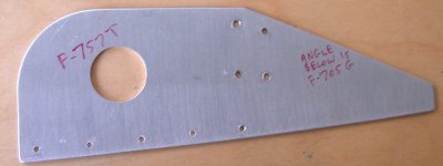 This
is the F757T from the LT side, after drilling out the temporary pop
rivets. The plans called for a square hole in this (for a tipup), but
I assumed it was just for an access hole, like on the aft F-631As, so I just
used a hole saw; much quicker and easier. NOTE: I Later found
out it should have been a square hole. It doesn't affect anything but
appearance, but it isn't right. The tipup canopy frame latching
fingers go through the hole.
This
is the F757T from the LT side, after drilling out the temporary pop
rivets. The plans called for a square hole in this (for a tipup), but
I assumed it was just for an access hole, like on the aft F-631As, so I just
used a hole saw; much quicker and easier. NOTE: I Later found
out it should have been a square hole. It doesn't affect anything but
appearance, but it isn't right. The tipup canopy frame latching
fingers go through the hole. 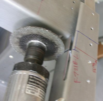 Here
is a somewhat fuzzy pic of me making these dangerous cuts to the
F-721B. One slip of the cutter, and I am DOOMED, especially when
making that cut right over the upper longeron. I slipped a piece of
scrap in between the 2 pieces, to protect the longeron.
Here
is a somewhat fuzzy pic of me making these dangerous cuts to the
F-721B. One slip of the cutter, and I am DOOMED, especially when
making that cut right over the upper longeron. I slipped a piece of
scrap in between the 2 pieces, to protect the longeron. 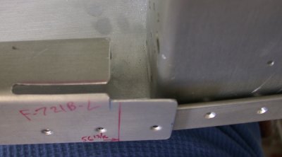 Here
is what the F-721B is supposed to look like. This is after much filing
and edge smoothing.
Here
is what the F-721B is supposed to look like. This is after much filing
and edge smoothing. 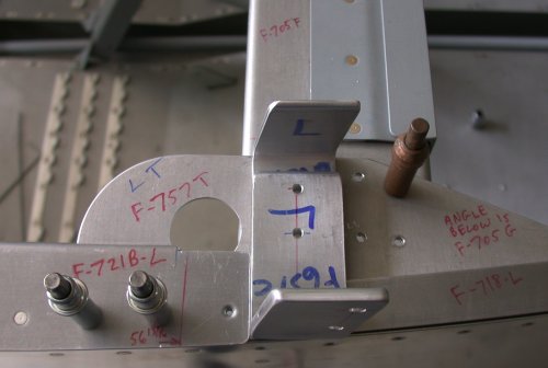 Now
it makes sense as to how the F-631C and D brackets fit in there. The
other thing that was throwing me was that the 2 holes in the F-631C were
obviously supposed to go through the D, but the outboard hole in the C was
right at the edge of the metal on the D, so I knew something was not
right. Eventually, I figured out that the C goes on the OUTside
of the F-631 assy, and the D goes on the INside of it. So, now
everything is fine, and I was finally able to measure between the inboard
sides of the 2 F-631C angles. This angle is exactly where it's
supposed to go. The fwd corner (LT in this pic) of the outside is even
with the outside edge of the upper longeron. The aft corner hangs out
over the longeron and skin. Later, a very tricky job is going to be to
trim those Cs so the entire outboard edge of the C is flush with the outer
part of the longeron. I'll use my mill, but it'll probably take quite
an effort to get the machine set up for the cut.
Now
it makes sense as to how the F-631C and D brackets fit in there. The
other thing that was throwing me was that the 2 holes in the F-631C were
obviously supposed to go through the D, but the outboard hole in the C was
right at the edge of the metal on the D, so I knew something was not
right. Eventually, I figured out that the C goes on the OUTside
of the F-631 assy, and the D goes on the INside of it. So, now
everything is fine, and I was finally able to measure between the inboard
sides of the 2 F-631C angles. This angle is exactly where it's
supposed to go. The fwd corner (LT in this pic) of the outside is even
with the outside edge of the upper longeron. The aft corner hangs out
over the longeron and skin. Later, a very tricky job is going to be to
trim those Cs so the entire outboard edge of the C is flush with the outer
part of the longeron. I'll use my mill, but it'll probably take quite
an effort to get the machine set up for the cut. 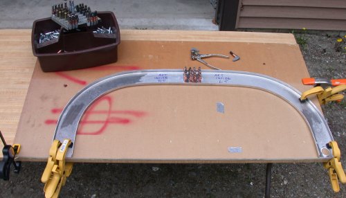 Once
I finally got my true width dimension to use, I laid out the width and
height measurements on this plywood cut from a Van's crate, trimmed the ends
of the aft F-631As, clamped them down, and drilled and clecoed the F-631E to
them, as the first step of several in tying them tightly together. I
drilled right into the plywood, and clecoed the parts right to the table,
further adding to the rigidity of holding this thing flat and right where I
wanted it.
Once
I finally got my true width dimension to use, I laid out the width and
height measurements on this plywood cut from a Van's crate, trimmed the ends
of the aft F-631As, clamped them down, and drilled and clecoed the F-631E to
them, as the first step of several in tying them tightly together. I
drilled right into the plywood, and clecoed the parts right to the table,
further adding to the rigidity of holding this thing flat and right where I
wanted it. 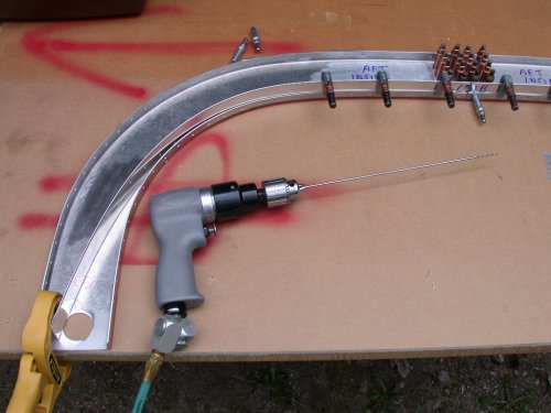 Here
is the start of clamping, drilling, and clecoing the lower F-631B strap to
the 2 aft F-631As. As it says in the manual, be sure to center the B,
clamp it tightly, start in the center and work out a couple holes at a time
on each side, being sure the B stays pushed down tightly into the web of the
631As as you go along. The As are clamped and clecoed to the plywood,
which in turn is clamped to the table.
Here
is the start of clamping, drilling, and clecoing the lower F-631B strap to
the 2 aft F-631As. As it says in the manual, be sure to center the B,
clamp it tightly, start in the center and work out a couple holes at a time
on each side, being sure the B stays pushed down tightly into the web of the
631As as you go along. The As are clamped and clecoed to the plywood,
which in turn is clamped to the table.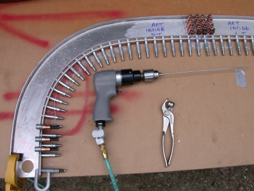 Here is the lower F-631B completely clecoed to the aft F-631As. Again,
be sure to keep the radiused edge of the B pushed tightly into the web of
the As as you work from the center out. The B will tend to climb out
as you go along, especially in the tightest part of the radius, if you don't
watch out for it. That tendency is even more prevalent when you start
doing the upper F-631B-L; the outer ends of the B-L keep trying to spring
out of the channel as you go along. Just do a couple holes at a time,
each side of center, use a cleco in every hole, and use clamps a couple
holes ahead of you as you move along.
Here is the lower F-631B completely clecoed to the aft F-631As. Again,
be sure to keep the radiused edge of the B pushed tightly into the web of
the As as you work from the center out. The B will tend to climb out
as you go along, especially in the tightest part of the radius, if you don't
watch out for it. That tendency is even more prevalent when you start
doing the upper F-631B-L; the outer ends of the B-L keep trying to spring
out of the channel as you go along. Just do a couple holes at a time,
each side of center, use a cleco in every hole, and use clamps a couple
holes ahead of you as you move along. 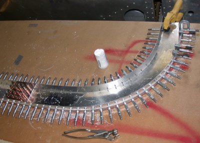 Here
are both the F-631B and F-631B-L (L is for Long, not for Left here), fully
clecoed into place. Now, this assembly is ready for the fwd
F-631As. The clecoes holding the F-631E plate in there will have to be
removed to get the 2 fwd F-631As on over the 631B straps. You'll also
need to unclamp the assembly from the table, so you can clamp the fwd 631As
to the aft 631As.
Here
are both the F-631B and F-631B-L (L is for Long, not for Left here), fully
clecoed into place. Now, this assembly is ready for the fwd
F-631As. The clecoes holding the F-631E plate in there will have to be
removed to get the 2 fwd F-631As on over the 631B straps. You'll also
need to unclamp the assembly from the table, so you can clamp the fwd 631As
to the aft 631As.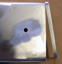 Before you put the fwd 631As on, don't forget to trim the ends in the
middle, to match what you had to trim on the aft A pieces to set your
width. Lay each one on, starting at the bottom end, and mark each end
where is is longer than the aft 631A in the middle.
Before you put the fwd 631As on, don't forget to trim the ends in the
middle, to match what you had to trim on the aft A pieces to set your
width. Lay each one on, starting at the bottom end, and mark each end
where is is longer than the aft 631A in the middle.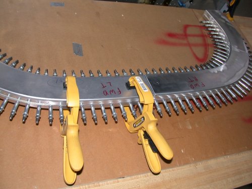 Here are
the 2 fwd 631As, laid into place. I started doing the LT side
first. When I did the aft 631As, I did one strap at a time, starting
in the middle, alternating from one 631A to the other. When
you cleco the fwd 631As, you'll want to work on one 631A at a time,
alternating from upper to lower strap as you work from the center toward the
outside. Clamp as necessary to achieve a 1.5" width of the
completed assembly. You'll have to clamp most tightly at the tightest
part of the radius. NOTE: As you'll
read
Here are
the 2 fwd 631As, laid into place. I started doing the LT side
first. When I did the aft 631As, I did one strap at a time, starting
in the middle, alternating from one 631A to the other. When
you cleco the fwd 631As, you'll want to work on one 631A at a time,
alternating from upper to lower strap as you work from the center toward the
outside. Clamp as necessary to achieve a 1.5" width of the
completed assembly. You'll have to clamp most tightly at the tightest
part of the radius. NOTE: As you'll
read 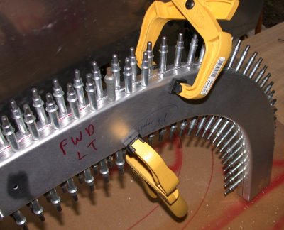 Here I am,
working my way around the LT fwd 631A, alternating from top to bottom as I
go.
Here I am,
working my way around the LT fwd 631A, alternating from top to bottom as I
go.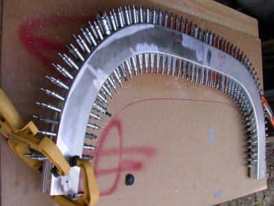 Here is the nearly completed F-631 assembly. Note the mix of silver
and copper clecoes. I didn't have enough silver ones to do the job
(and all the holes will eventually be 1/8"), so as I got near the end,
I had to steal silver clecoes from other, already done, holes, and drill the
existing holes to 1/8", so every hole had a cleco. I used a cleco
in every hole to help ensure that nothing moved during this process.
When you're putting those F-631B straps in, they don't want to be there, so
they need lots of clamping and clecoing to make sure they stay where you
want them.
Here is the nearly completed F-631 assembly. Note the mix of silver
and copper clecoes. I didn't have enough silver ones to do the job
(and all the holes will eventually be 1/8"), so as I got near the end,
I had to steal silver clecoes from other, already done, holes, and drill the
existing holes to 1/8", so every hole had a cleco. I used a cleco
in every hole to help ensure that nothing moved during this process.
When you're putting those F-631B straps in, they don't want to be there, so
they need lots of clamping and clecoing to make sure they stay where you
want them. 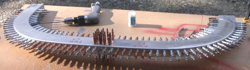 After I got all the clecoes into the 631As & 631Bs, I drilled and
clecoed the fwd F-631E into place. Then I started removing one silver
cleco at a time, drilling the hole out to 1/8", and installing a copper
cleco, until I ran out of copper clecoes. I will finish this on
May 6th, when my order of more clecoes arrives from Avery.
After I got all the clecoes into the 631As & 631Bs, I drilled and
clecoed the fwd F-631E into place. Then I started removing one silver
cleco at a time, drilling the hole out to 1/8", and installing a copper
cleco, until I ran out of copper clecoes. I will finish this on
May 6th, when my order of more clecoes arrives from Avery. 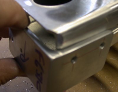 This shows the
radius that needs to be added to the bottom of each aft F631A, so it fits
nicely into the F631C angle.
This shows the
radius that needs to be added to the bottom of each aft F631A, so it fits
nicely into the F631C angle.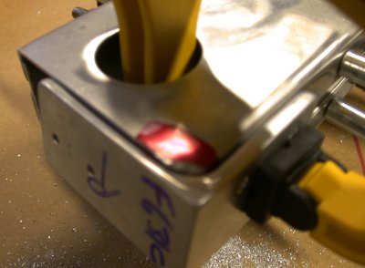 This shows
the F631C clamped into place on the F631A, after the F631A bottom radius was
made. The bottom of the C sits inside the A. This is an initial
fitting, before trimming more to get the height set. When the height
is set, I ended up with the aft portion of the F631C flush with the edge of
the bottom of the F631A.
This shows
the F631C clamped into place on the F631A, after the F631A bottom radius was
made. The bottom of the C sits inside the A. This is an initial
fitting, before trimming more to get the height set. When the height
is set, I ended up with the aft portion of the F631C flush with the edge of
the bottom of the F631A.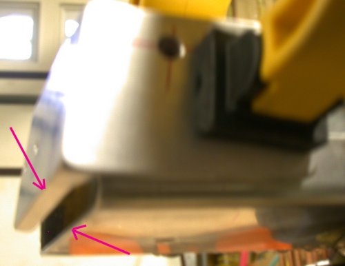 This shows
how the fwd portion of the F631C sticks out from the bottom of the F631A,
while, as show in the previous pic, the aft portion of the bottom of the C
will be about flush with the aft portion of the bottom of the A.
This shows
how the fwd portion of the F631C sticks out from the bottom of the F631A,
while, as show in the previous pic, the aft portion of the bottom of the C
will be about flush with the aft portion of the bottom of the A.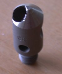 In my Avery
order, I also got a new one-hole deburring cutter. I had been using
the 3-bladed cutter, because I was told at Alexander technical Center that
they were better.
In my Avery
order, I also got a new one-hole deburring cutter. I had been using
the 3-bladed cutter, because I was told at Alexander technical Center that
they were better.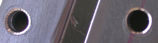 As
you can see here, the one-hole cutter does a MUCH better job. The hole
on the LT was deburred with the 3-bladed deburring cutter. The one on
the RT was with the new one-hole cutter. The one-hole
cutters are also very easy to sharpen. I've also now switched all my
countersink tools over to the one-hole design.
As
you can see here, the one-hole cutter does a MUCH better job. The hole
on the LT was deburred with the 3-bladed deburring cutter. The one on
the RT was with the new one-hole cutter. The one-hole
cutters are also very easy to sharpen. I've also now switched all my
countersink tools over to the one-hole design.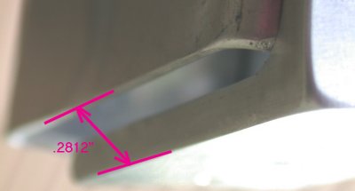 Here's
another pic showing where the difference in height between the F631A by
itself and with the F631C is measured on the forward edges.
Here's
another pic showing where the difference in height between the F631A by
itself and with the F631C is measured on the forward edges. As
mentioned in the pics above, the aft portion of the F631C will be about
flush with the aft portion of the F631A when you've got your A radius set
and the correct frame height set.
As
mentioned in the pics above, the aft portion of the F631C will be about
flush with the aft portion of the F631A when you've got your A radius set
and the correct frame height set.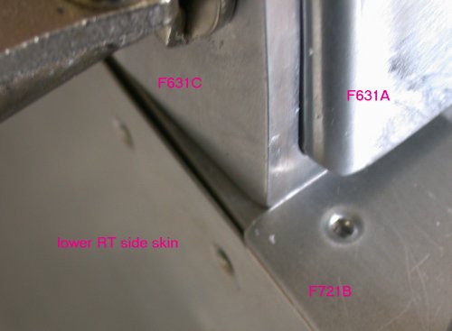 This pic
shows how the F631 frame assemble came out 1/8" too narrow. This
is the RT side. The LT side outer edge of the F631C is flush with the
outside of the upper longeron. LOOKING AT THIS PICTURE ALSO MAKES ME
THINK THE OUTER EDGE OF THE F631C SHOULD BE FLUSH WITH THE OUTSIDE OF THE
SKIN, NOT THE OUTSIDE OF THE LONGERON, AS I THOUGHT THE PLANS SAID.
THE SKIN THAT GOES OVER THE F631C ALSO GOES OVER THE SKIN BELOW
IT. *** I WILL HAVE TO CHECK THIS OUT.
This pic
shows how the F631 frame assemble came out 1/8" too narrow. This
is the RT side. The LT side outer edge of the F631C is flush with the
outside of the upper longeron. LOOKING AT THIS PICTURE ALSO MAKES ME
THINK THE OUTER EDGE OF THE F631C SHOULD BE FLUSH WITH THE OUTSIDE OF THE
SKIN, NOT THE OUTSIDE OF THE LONGERON, AS I THOUGHT THE PLANS SAID.
THE SKIN THAT GOES OVER THE F631C ALSO GOES OVER THE SKIN BELOW
IT. *** I WILL HAVE TO CHECK THIS OUT. 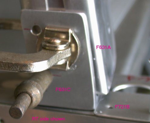 This pic
shows what I was talking about by drilling only the lower hole from the
F631C into the aft F631A. Then the 2 pieces can pivot, allowing you to
make sure the F631C is sitting flat on the longeron, and the top of the
F631A frame is set to the right distance from vertical (it tips back).
Don't drill that upper hole until your F631A angle is set. A very
small difference in hole placement here makes a much bigger difference in
where the top of the F6731A ends up.
This pic
shows what I was talking about by drilling only the lower hole from the
F631C into the aft F631A. Then the 2 pieces can pivot, allowing you to
make sure the F631C is sitting flat on the longeron, and the top of the
F631A frame is set to the right distance from vertical (it tips back).
Don't drill that upper hole until your F631A angle is set. A very
small difference in hole placement here makes a much bigger difference in
where the top of the F6731A ends up. 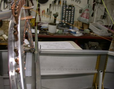 Here's
the setup for measuring the aft tilt of the F631A cabin frame. A plumb
bob hangs from the ceiling over the center fuselage. A straightedge is
laid along the fwd bottom edges of the F631A assy. Get the plumb bob
over the straightedge, then just measure back 2 7/8" from the string to
the fwd top edge of the F631A assy. I used a piece of wire from one of
the top clecoes to the instrument panel to hold the F631A cabin frame assy
held tipped back at the right angle. Then I measured the distance from
the plumb bob string to the F631A frame, and adjusted the length of the
wire, until I had it just right.
Here's
the setup for measuring the aft tilt of the F631A cabin frame. A plumb
bob hangs from the ceiling over the center fuselage. A straightedge is
laid along the fwd bottom edges of the F631A assy. Get the plumb bob
over the straightedge, then just measure back 2 7/8" from the string to
the fwd top edge of the F631A assy. I used a piece of wire from one of
the top clecoes to the instrument panel to hold the F631A cabin frame assy
held tipped back at the right angle. Then I measured the distance from
the plumb bob string to the F631A frame, and adjusted the length of the
wire, until I had it just right. 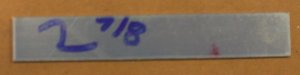 The
fwd top of the F631A cabin frame needs to be 2 7/8" aft of plumb with
the bottom forward edge of the F631A. Rather than screw around trying
to see which little mark on the rule the plumb line was next to, I found it
much easier to just cut a scrap of aluminum to the correct distance, and use
that as a go-nogo gage.
The
fwd top of the F631A cabin frame needs to be 2 7/8" aft of plumb with
the bottom forward edge of the F631A. Rather than screw around trying
to see which little mark on the rule the plumb line was next to, I found it
much easier to just cut a scrap of aluminum to the correct distance, and use
that as a go-nogo gage. 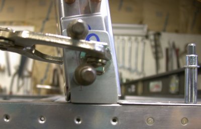 Once you
get that cabin frame angle set, go ahead and match drill the upper hole in
the F631A, through the upper hole in the F631C.
Once you
get that cabin frame angle set, go ahead and match drill the upper hole in
the F631A, through the upper hole in the F631C. 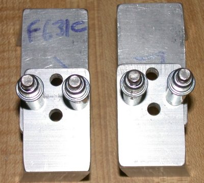 Then
clamp the F631D angles in place, so they fit nice & flat against both
the inside of the F631A and against the base of the F631C. Then drill
the 2 little keeper rivet holes (drilled & clecoed here), then the two
1/4" bolt holes.
Then
clamp the F631D angles in place, so they fit nice & flat against both
the inside of the F631A and against the base of the F631C. Then drill
the 2 little keeper rivet holes (drilled & clecoed here), then the two
1/4" bolt holes. 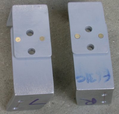 Here are the 2
sets of F631C&D angles riveted together, to form a channel. Prime
the 2 pieces where they overlap, before riveting.
Here are the 2
sets of F631C&D angles riveted together, to form a channel. Prime
the 2 pieces where they overlap, before riveting. 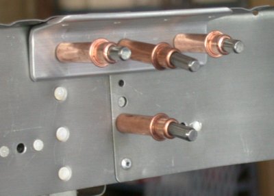 Here is the
F732B angle clecoed to the F706 aft baggage bulkhead. The position of
the line of holes is specced on the drawing. Drill one hole in the
center, along the spec line, then cleco it to the F706 and match-drill the
remaining holes. This puts the F732B right up tight against the
flange of the F706. I have to get with Van's and see how they
recommend handling the skin rivets that will be on top of the F732B.
The plans don't spec them long enough to go all the way through the F732B,
nor do the plans show the rivets going through the F732B, but I don't see
any other way to do it. If the skin is riveted first, then the F732B
won't be able to sit high enough.
Here is the
F732B angle clecoed to the F706 aft baggage bulkhead. The position of
the line of holes is specced on the drawing. Drill one hole in the
center, along the spec line, then cleco it to the F706 and match-drill the
remaining holes. This puts the F732B right up tight against the
flange of the F706. I have to get with Van's and see how they
recommend handling the skin rivets that will be on top of the F732B.
The plans don't spec them long enough to go all the way through the F732B,
nor do the plans show the rivets going through the F732B, but I don't see
any other way to do it. If the skin is riveted first, then the F732B
won't be able to sit high enough. 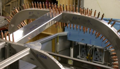 Once you get
the F631A cabin frame assy angle set, then you lock it into place with the
F632A channel. The F632A channel sits on top of the F732D angle on the
fwd end and UNDER the F732B on the aft end.
Once you get
the F631A cabin frame assy angle set, then you lock it into place with the
F632A channel. The F632A channel sits on top of the F732D angle on the
fwd end and UNDER the F732B on the aft end. 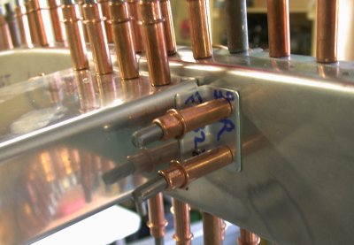 After clecoing
the F632A channel, locking the F631A cabin frame into place, match drill and
cleco the
F732E angles to the fwd end of the F632A channel.
After clecoing
the F632A channel, locking the F631A cabin frame into place, match drill and
cleco the
F732E angles to the fwd end of the F632A channel. 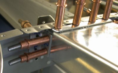 and cleco the
F732C angles to the aft end of the F632A. Just aft of the 4 top
clecoes, you can see where the 4 skin rivets are right over the F732B, which
is tight up against the bottom of the F706 bulkhead flange.
and cleco the
F732C angles to the aft end of the F632A. Just aft of the 4 top
clecoes, you can see where the 4 skin rivets are right over the F732B, which
is tight up against the bottom of the F706 bulkhead flange. 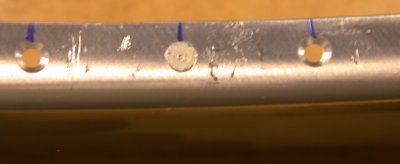 Due to
the changing curved nature of the F631A frame pieces, each countersunk hole
around the outside and inside perimeters required a bit different setting on
the countersink cage. So, each hole had to be individually worked on,
tested with a rivet, and marked as complete, as in this pic.
Due to
the changing curved nature of the F631A frame pieces, each countersunk hole
around the outside and inside perimeters required a bit different setting on
the countersink cage. So, each hole had to be individually worked on,
tested with a rivet, and marked as complete, as in this pic.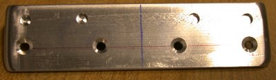 This shows the
counterbores put into the F732B, to clear the F774 top skin rivet heads
This shows the
counterbores put into the F732B, to clear the F774 top skin rivet heads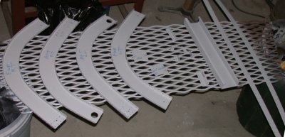 Here
are all the F631 assembly cabin frame (roll bar) components primed.
Here
are all the F631 assembly cabin frame (roll bar) components primed.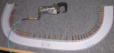 Lay it
out flat, cleco the F631 straps into place, and start squeezing all the solid
rivets for the fwd half. Notice the As are not clamped down.
Mistake #1. You'll be hearing more about this later.
Lay it
out flat, cleco the F631 straps into place, and start squeezing all the solid
rivets for the fwd half. Notice the As are not clamped down.
Mistake #1. You'll be hearing more about this later.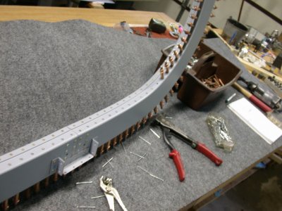 After
all the fwd rivets are squeezed in place, begin putting in the CS4-4 pop
rivets for the aft half. Note that the frame is standing up, and not
clamped down at all. Big Mistake #2. I had assumed that, once
the pieces had been clamped down, drilled, and clecoed in the initial
hole-drilling process, the assembly would remain true. This turned out
to be false. Also, note that when I put this together initially, I had
started with the aft half. But, when I did the final assembly, I
started with squeezing the solid rivets in the FORWARD half. That,
too, may have contributed to the twisting that followed.
After
all the fwd rivets are squeezed in place, begin putting in the CS4-4 pop
rivets for the aft half. Note that the frame is standing up, and not
clamped down at all. Big Mistake #2. I had assumed that, once
the pieces had been clamped down, drilled, and clecoed in the initial
hole-drilling process, the assembly would remain true. This turned out
to be false. Also, note that when I put this together initially, I had
started with the aft half. But, when I did the final assembly, I
started with squeezing the solid rivets in the FORWARD half. That,
too, may have contributed to the twisting that followed.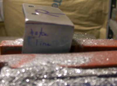 This is how
the outside leg of each F631C gets filed to a taper, as per the line.
This is how
the outside leg of each F631C gets filed to a taper, as per the line.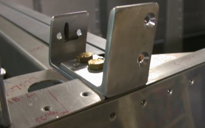 Here is one of the F631C/D assemblies, bolted into place, tapered, and
countersunk for the frame attachment screws. The taper is on the RT
(aft) in this pic, so it's a bit hard to see. You have to do the taper
first, then the countersinking, so the countersinks are perpendicular to the
altered face. The tapered filing makes the outside of the F631C
flush with the outside fuselage skin.
Here is one of the F631C/D assemblies, bolted into place, tapered, and
countersunk for the frame attachment screws. The taper is on the RT
(aft) in this pic, so it's a bit hard to see. You have to do the taper
first, then the countersinking, so the countersinks are perpendicular to the
altered face. The tapered filing makes the outside of the F631C
flush with the outside fuselage skin.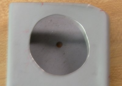 In
trial-fitting the frame, I found out there was no way I'd get my fingers
into the holes in the aft frame pieces, to get the nuts onto the
screws. So, I enlarged the holes until I could get two fingers,
holding a nut, into them. I will cover these unsightly holes with a
cover plate, once the frame is final-bolted on and torqued.
In
trial-fitting the frame, I found out there was no way I'd get my fingers
into the holes in the aft frame pieces, to get the nuts onto the
screws. So, I enlarged the holes until I could get two fingers,
holding a nut, into them. I will cover these unsightly holes with a
cover plate, once the frame is final-bolted on and torqued.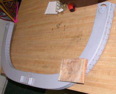 This shows the
amount of fwd/aft twist in the RT side of the completed cabin frame (roll
bar). This was after I had already removed the CCW twisting in each
leg. Quite irritating, especially after all the trouble (and clecoes)
I went to, trying to make sure this F631 assembly was as clamped and rigid
as possible! After a couple conversations with support people at Van's about
this problem, I decided to drill out all the CS4-4 pop rivets, get it back
to flat, then redo the pop rivets in oversized CherryMax rivets. I
knew that redrilling the realigned holes would result in enlarged holes, but
the CherryMax heads are extra large, and I found in the ACS catalog that you
can get CherryMax pop rivets with shanks that are 1/64" oversize.
A lifesaver! I ordered plenty of them.
This shows the
amount of fwd/aft twist in the RT side of the completed cabin frame (roll
bar). This was after I had already removed the CCW twisting in each
leg. Quite irritating, especially after all the trouble (and clecoes)
I went to, trying to make sure this F631 assembly was as clamped and rigid
as possible! After a couple conversations with support people at Van's about
this problem, I decided to drill out all the CS4-4 pop rivets, get it back
to flat, then redo the pop rivets in oversized CherryMax rivets. I
knew that redrilling the realigned holes would result in enlarged holes, but
the CherryMax heads are extra large, and I found in the ACS catalog that you
can get CherryMax pop rivets with shanks that are 1/64" oversize.
A lifesaver! I ordered plenty of them.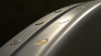 This shows how poorly the CS4-4 rivets sit in the countersunk holes.
After all this time, I finally figured out, from my conversation with Ken at
Van's, that the reason the CS4 rivets don't sit that well is
because they have 120 degree heads, and these countersunk holes, and all the
solid rivets and CherryMax rivets, are 100 degree heads. Straightening
the frame and redrilling the holes will result in enlarged holes.
Fortunately, I found that ACS carries oversized CherryMay rivets, so they
will not only fit these 100 degree countersunk holes much better, the larger
formed head of a CherryMax rivet and the oversized shank will take care of
any oversized holes. Ken said I can even go to 5/32" CherryMax
rivets if the holes get enlarged that much from drilling out the CS4-4
rivets and straightening the frame.
This shows how poorly the CS4-4 rivets sit in the countersunk holes.
After all this time, I finally figured out, from my conversation with Ken at
Van's, that the reason the CS4 rivets don't sit that well is
because they have 120 degree heads, and these countersunk holes, and all the
solid rivets and CherryMax rivets, are 100 degree heads. Straightening
the frame and redrilling the holes will result in enlarged holes.
Fortunately, I found that ACS carries oversized CherryMay rivets, so they
will not only fit these 100 degree countersunk holes much better, the larger
formed head of a CherryMax rivet and the oversized shank will take care of
any oversized holes. Ken said I can even go to 5/32" CherryMax
rivets if the holes get enlarged that much from drilling out the CS4-4
rivets and straightening the frame.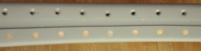 This shows how the hole alignment changed once I had drilled out all the pop
rivets on the RT side and reefed on the frame until it lay flat.
This shows how the hole alignment changed once I had drilled out all the pop
rivets on the RT side and reefed on the frame until it lay flat.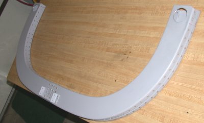 After removing the RT side pop rivets and reefing on the frame, it
lays nice and flat now.
After removing the RT side pop rivets and reefing on the frame, it
lays nice and flat now.