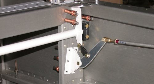
 And here it is with all the parts installed.
 CANOPY August, 2004
Aug 3 - Finally trying to get myself back up to speed on the plane after being away at OSH for a week. Fine tuned fit of WD617 to oval holes in F705. Fit the VS411 brackets. Prep C605 beam idler and install it. Bend and install C606 links. The plans don't seem to spell out what bolts to use for all this, so I just figured out what sizes I need here. Adjusted length of C710 rod so that WD617 goes fully into the oval holes in F705. 4.0 hr
And here it is with all the parts installed.
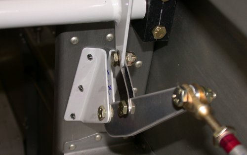 Here's the detail view of the rear canopy latch parts. You have to
bend & twist those little C606 links to fit. Like the manual says,
it becomes pretty obvious what's needed once you start doing it.
Here's the detail view of the rear canopy latch parts. You have to
bend & twist those little C606 links to fit. Like the manual says,
it becomes pretty obvious what's needed once you start doing it.
Aug 4 - Continue adjusting length of C710 rod. Trim 0.1900" off one end in my lathe. Dimple fuselage LT side skin and countersink upper & lower C712s. Clean parts & prime. Pack up to go to the track. 2.5 hr
Aug 5-8 - racing at NHIS; process pics & update web site during down time 12.5 hr doc
Aug 10 - cleco and rivet C712 angles to skin. 0.5 hr
Aug 11 - finish riveting C712 angles to skin. Start in in "Fit Canopy Frame to Fuseleage" portion of manual. Put UHMW tape on bottom fwd edge of C702. Find & mark centerline of WD716 aft rod. As per manual, spent a HUGE amount of time filing the fwd rib top flange of the WD716 so it's 90 degrees. I don't know why it needs to be filed, and not just bent, but I was a good boy & did what I was told. I filed on that thing for hours. Then I clecoed the C702 skin onto the frame. It did not fit well at all, as described on both Dan Checkoway's and Walter Tondu's (and no doubt numerous others') web sites, as well as what I encountered. 3.5 hr
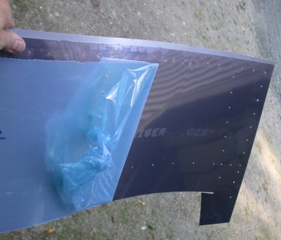
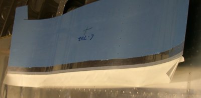 Here's the
C702 canopy skin, with 3/8" of HDPE tape on the bottom fwd edge, as per
the manual.
Here's the
C702 canopy skin, with 3/8" of HDPE tape on the bottom fwd edge, as per
the manual.
Aug 12 - beveled aft edge of canopy frame hinge blocks, as well as fwd edge of canopy hinges, for a much easier slide-in fit when putting the canopy frame hinges into the hinge blocks. Grrrrr - found that, somehow, when the F771 fwd skin is clecoed on, it slightly squeezes the LT hinge blocks together a bit, and the LT hinge WILL NOT go it, even with the aforementioned bevels. If I put the hinge in first, it goes in OK, but then the outer F771 rivet holes don't line up. As I said, grrrrr. Removed skin, canopy frame, and LT hinge blocks. Decided that I can fix the problem by taking material off the back side (outboard) edge of the outboard spacer (C618), so I spent hours sanding the back of that. I also noted that Dan Checkoway is now selling his web site on a CD, so I ordered that. It's a tad expensive, but actually a real bargain compared to the Orndorff tapes, for several reasons. First, the media; it's random access, not sequential access. You don't have to go through a tape to see something; you go right to where you want. You can search for things. Second, it's current and very detailed. Ornforff's tapes are obsolete RV-6 stuff, and I found them to be only marginally useful on a new RV-7 Quick Build. 2.75 hr
 Things will be much
better for you if you file a bevel on the fwd edge of the hinge arms.
Remember; the canopy frame, and these arms, will be going in and out of
those hinge blocks at least a hundred times while you're fitting this frame
to the fuselage.
Things will be much
better for you if you file a bevel on the fwd edge of the hinge arms.
Remember; the canopy frame, and these arms, will be going in and out of
those hinge blocks at least a hundred times while you're fitting this frame
to the fuselage.
 Do it on the aft
edges of the hinge blocks, too.
Do it on the aft
edges of the hinge blocks, too.
![]() Coarse
sandpaper and about 2 hours of sanding removed no more than 1/64" off
the back side of this spacer. This stuff is TOUGH! The canopy hinge and F771 fwd skin fit
better afterward, though.
Coarse
sandpaper and about 2 hours of sanding removed no more than 1/64" off
the back side of this spacer. This stuff is TOUGH! The canopy hinge and F771 fwd skin fit
better afterward, though.
Aug 13 - opened up bag of parts for canopy frame reinforcement kit - all the rivets (of different sizes) are all just dumped in there. So, I had fun sorting that mess out for about half an hour. Oriented the pieces and started making the reinforcing flanges in the lightening holes in the F7128Bs and C7128A. Cleco and drill C702 skin to the aft tubing on the WD716 canopy frame, at least for the holes that lined up. Remove and flip C619s over for more clearance for hinge. Redrilled hinge block holes for easier bolt fit. Ended up with a huge long list of poor fit problems to email to Van's about. 6.0 hr
 Using the Cleaveland edge bending tool to start flaring the lightening holes
in the canopy frame reinforcing kit.;
Using the Cleaveland edge bending tool to start flaring the lightening holes
in the canopy frame reinforcing kit.;
 Once I got the flares started with the Cleaveleand tool, I made this tool
out of aluminum bar stock to finish flaring them. I tried it with
wood, but the wood split open, so I made this. It worked great.
Once I got the flares started with the Cleaveleand tool, I made this tool
out of aluminum bar stock to finish flaring them. I tried it with
wood, but the wood split open, so I made this. It worked great.
 When I was flaring the
lightening holes on the C7128A, I got a bit carried away and flared it
considerably more than the plans called for. It was going so well, and
I figured I'd get even better stiffness by flaring to more than the 20 or 30
degrees the plans specced. I ended up flaring them to nearly 90
degrees. Unfortunately, there's a reason to not try to bend 2020T3 too
much; it cracks. One hole had these 2 cracks. I stop-drilled
them, and debated strongly for quite awhile about whether or not to replace
the C7128A. Even though I was ordering some other parts, I decided
this would really be fine. I may yet replace it, though. It's
not a big deal - the whole thing is optional anyway.
When I was flaring the
lightening holes on the C7128A, I got a bit carried away and flared it
considerably more than the plans called for. It was going so well, and
I figured I'd get even better stiffness by flaring to more than the 20 or 30
degrees the plans specced. I ended up flaring them to nearly 90
degrees. Unfortunately, there's a reason to not try to bend 2020T3 too
much; it cracks. One hole had these 2 cracks. I stop-drilled
them, and debated strongly for quite awhile about whether or not to replace
the C7128A. Even though I was ordering some other parts, I decided
this would really be fine. I may yet replace it, though. It's
not a big deal - the whole thing is optional anyway.
Aug 14 - spent a couple hours processing pictures & composing the following email to Van's about all the fit problems with the canopy frame: 2.0 hr
EMAIL TO VAN'S ABOUT NUMEROUS POOR FIT PROBLEMS, AND THE REPLIES:
Van's reply is in italics
I have run into several problems with the fit of the 2 fwd top fuse skins and the tipup canopy frame. I understand other builders have experienced similar problems, but I don’t know whether or not they have brought the problems to your attention. I hope you’ll address these problems for future builders, and help me get around them.
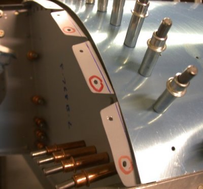
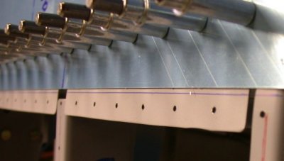
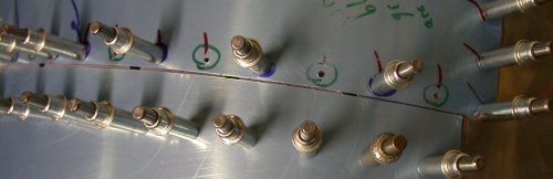
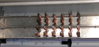
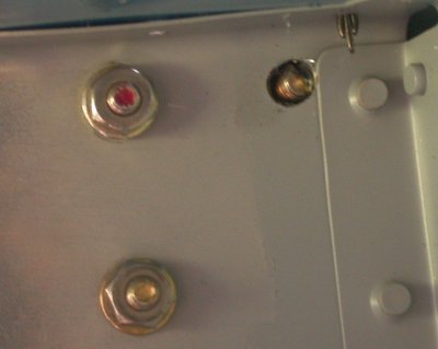
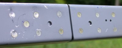
 The
hole matching between the F771 fwd skin and the F768B LT & RT outboard
subpanels is poor. The holes in
the top of the skin matched up to the F768A center subpanel as per Van’s
usual standards. But when I did
the match drilling for the F771 top skin and the F768B outboard subpanels,
the holes did not line up. The F771 skin is off in these pics, and the
misaligned holes have been circled in red.
I know it isn’t anything I did wrong, because the upper hole in
each section of the flange aligned properly.
The next hole on the same flange section did not line up well at all,
and then the next hole, in the next section, lined up correctly again.
As you can see in the pics, it gets worse as I progress down toward
the bottom of the skin. I have
the problem on both sides. What
do you recommend I do about this problem?
The
hole matching between the F771 fwd skin and the F768B LT & RT outboard
subpanels is poor. The holes in
the top of the skin matched up to the F768A center subpanel as per Van’s
usual standards. But when I did
the match drilling for the F771 top skin and the F768B outboard subpanels,
the holes did not line up. The F771 skin is off in these pics, and the
misaligned holes have been circled in red.
I know it isn’t anything I did wrong, because the upper hole in
each section of the flange aligned properly.
The next hole on the same flange section did not line up well at all,
and then the next hole, in the next section, lined up correctly again.
As you can see in the pics, it gets worse as I progress down toward
the bottom of the skin. I have
the problem on both sides. What
do you recommend I do about this problem?
On those tabs on the sub panel that have the bad hole match, add an extra rivet in between the good hole and the bad hole. It looks like you only need to add three new rivets, one per tab.
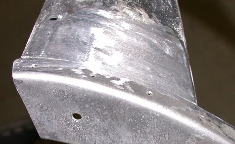
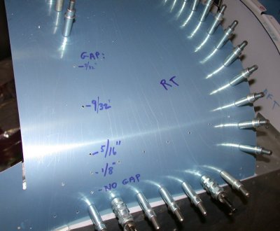 The C702 skin does not fit the WD716 frame at all, on the outermost part of
the aft section. The problem is
with the way the frame is made. The
rod is welded to the inside of the frame base, when it should be welded so
the outside edge of the tubing is flush with the outside of the frame base.
The tubing that forms the aft part of the frame turns inside the
outer part of the frame at the outside edges, disrupting the smooth curve,
and departing from the natural line the skin should take to get to the edge.
It’s hard to describe. After
I match drilled all the holes between the C702 skin and the tubing, I
measured & marked the gap depth of each hole that I did not drill
because of the gap. As you can
see, the skin fits the frame rod nicely across the top and starting down the
side, with a cleco in each hole. Then,
as it gets about halfway down the side, the rod is curved to the INside of
the frame base, while the bottom of the skin is going to the OUTside of the
frame base. This leaves a huge
gap. I can’t drill this or
try to pull it in – it’ll make a horrible mess.
It’s the same situation on both sides.
The bottom of the skin fits the frame, and it is clecoed, but I’m
left with this big gap above the bottom cleco.
What do you recommend I do about this problem?
The C702 skin does not fit the WD716 frame at all, on the outermost part of
the aft section. The problem is
with the way the frame is made. The
rod is welded to the inside of the frame base, when it should be welded so
the outside edge of the tubing is flush with the outside of the frame base.
The tubing that forms the aft part of the frame turns inside the
outer part of the frame at the outside edges, disrupting the smooth curve,
and departing from the natural line the skin should take to get to the edge.
It’s hard to describe. After
I match drilled all the holes between the C702 skin and the tubing, I
measured & marked the gap depth of each hole that I did not drill
because of the gap. As you can
see, the skin fits the frame rod nicely across the top and starting down the
side, with a cleco in each hole. Then,
as it gets about halfway down the side, the rod is curved to the INside of
the frame base, while the bottom of the skin is going to the OUTside of the
frame base. This leaves a huge
gap. I can’t drill this or
try to pull it in – it’ll make a horrible mess.
It’s the same situation on both sides.
The bottom of the skin fits the frame, and it is clecoed, but I’m
left with this big gap above the bottom cleco.
What do you recommend I do about this problem?
This is a common situation and we have the same thing on our RV-7A tip-up. The solution is to not put any rivets in the skin where the skin starts to separate from the tube. There is plenty of strength in the assembly and you can fill the gap later with microballoons and epoxy.
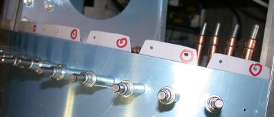
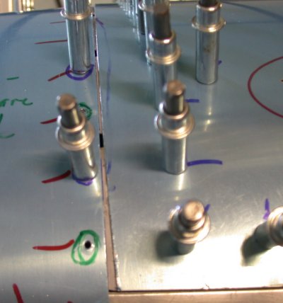
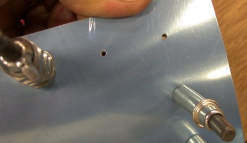 The C702 skin also does not fit the frame at the 2 fwd bottom corners.
The fwd and bottom parts of the skin match drilled and clecoed OK
until I got to the bottom 2 fwd holes.
As you can see in this pic,
one hole is off in one direction and the other is off in the other
direction. This is similar to
Problem #1. Because of what
happened in #1 above, I have not attempted to drill these 2 holes on each
side. What do you suggest I do
to deal with this?
The C702 skin also does not fit the frame at the 2 fwd bottom corners.
The fwd and bottom parts of the skin match drilled and clecoed OK
until I got to the bottom 2 fwd holes.
As you can see in this pic,
one hole is off in one direction and the other is off in the other
direction. This is similar to
Problem #1. Because of what
happened in #1 above, I have not attempted to drill these 2 holes on each
side. What do you suggest I do
to deal with this?
Remove the skin from the frame and file the triangular part so that it matches the curve of the front bow better. Then just go ahead and match drill the missmatched hole. It will hold just fine.
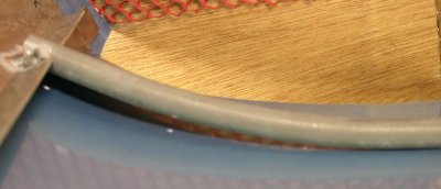
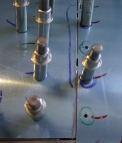
 The 2 top skins, the F771 fwd panel and the C702 canopy panel, are supposed
to butt up against each other. With
the canopy frame shoved as far fwd as it will go, there is about a 1/8”
gap between the skins.
Fwd is down in this pic. The
F771 panel has been removed, and the blue line you see marks the aft edge of
the F771. I also have an air
gap between the hinge and the C619 block, so that isn’t what’s keeping
it from coming more forward. What
is keeping it from coming more fwd is that the fwd edge of the canopy frame
is hitting the aft portion of the F768D seal flanges, on LT & RT.
What do I need to do about this; cut the 1/8” or so off the seal
flanges?
The 2 top skins, the F771 fwd panel and the C702 canopy panel, are supposed
to butt up against each other. With
the canopy frame shoved as far fwd as it will go, there is about a 1/8”
gap between the skins.
Fwd is down in this pic. The
F771 panel has been removed, and the blue line you see marks the aft edge of
the F771. I also have an air
gap between the hinge and the C619 block, so that isn’t what’s keeping
it from coming more forward. What
is keeping it from coming more fwd is that the fwd edge of the canopy frame
is hitting the aft portion of the F768D seal flanges, on LT & RT.
What do I need to do about this; cut the 1/8” or so off the seal
flanges?
There should be a gap between the hinges for the canopy skin to pass over the fwd skin when the canopy is raised. The skins should match from the hinges outboard. I don't know how to help on this one. The manual, section 9, under "FITTING THE CANOPY FRAME TO THE FUSELAGE" says to butt the skins together, then slip a .020 or .032 shim in between them. You may have overlooked that step. If cutting some off of the seal flange will allow the skins to butt of have a .020:gap, then that is the solution.
A suggestion – it would be very nice if the canopy frame reinforcing kit came with each rivet size in its own little bag, rather than all just dumped in together into the paper bag, resulting in lots of time wasted sorting out all those little rivets.I'll pass this along to the "Bag Man".
And
a question – at what point in the building of the canopy frame is it
recommended that I add the canopy frame reinforcing kit?
I would put the reinforcing kit on when ever it won't interfere with any other construction. For instance, we have a GPS antenna on the glare shield, so we needed a wire run in there.
One
more question; Page 9-2 of the manual says (para 2) that the bolt hole edge
distance on the C619 is critical and is used as a stop for the canopy frame.
I don’t understand this. What
difference does it make? What
defines how far forward the canopy hinge comes is the F771-to-C702 skin fit
(see #4 above). I know other
builders have had to trim the aft edge of the C619 to get the hinge forward
far enough. I don’t
understand the point in whether the hinge touches the C619 or not.
Does it really matter at all?
If the holes are in the right place, then no trimming should be necessary. It's no big deal if later a builder has to massage the parts a bit to get a good fit.
Aug 16 - still waiting for a reply from Van's to my canopy fit questions (questions above were sent Sat 8/14, but not answered until 8/17 evening). Decided to lay out and drill the C614 canopy frame tie plate. 1.5 hr
Aug 17-22 = at NHIS, racing and updating web site during down time
Aug 21 - noted from reading entries on Dan Checkoway's site that he found it's important to make sure the canopy frame skin is at least as high as the fwd fuselage skin when drilling those hinge bolt holes. I will have to be very careful when I do that. Also picked up a couple more tips from Walter Tondu's site about putting the headphone jacks in the bottom of the F632 cabin frame support channel, and about changing the 470 rivets to 426 on the flap motor brace, so the WD617 doesn't rub on them so much. Walter also has some great pics of the avionics access panels that he, Dan, Gary Newsted, Fred Stucklen, and others have put in. I'll be doing that, too. Also sent email to Bill Esther about the engraved fuel caps that Dan & Walter used. 3.0 hr
Aug 24 - Finally was able to get off the emails, avionics, and computer stuff, and get back to the PLANE. Marked where canopy frame shields the subpanel. Removed C702 skin so I can see why the canopy frame won't go any more forward. Filed the canopy seal flange lip some to help the weldment go forward. Filed down the aft edge of the RT C619 block, because the hinge arm was hitting it. Marked the LT F745 where I will eventually cut it off to make a custom rib between the subpanel and the instrument panel on the LT side. Filed fwd edge of triangular part of WD716 weldment, where it meets (and sticks out slightly from) the fwd channel on the weldment. That was tedious, but I eventually got it to a nice and smooth transition between the 2 pieces. Drill and cleco most all holes in canopy frame and C702 skin, except the holes over the plates that go from fwd to aft on the weldment, to tie in the tubing at the aft of the weldment. Skins now fit better, but it still isn't quite right. The bottom edges butt, but there's still a 1/8" gap in the center. Also, the skins are flush on top and on the bottom (sides), but midway through the curve, at about 45 degrees, the C702 skin is higher than the F771 skin. I don't know what I can do about that. Finally, I put together orders to Avery and ACS. 8.25 hr
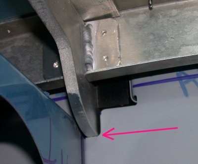
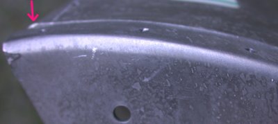 One of
the things Bruce Reynolds told me to do was file down the fwd bottom
triangular parts of the canopy frame weldment, so it's flush with the fwd
channel. You can see it isn't flush now, especially at the bottom
corner (LT in the pic), where the red arrow is pointing out a bump.
One of
the things Bruce Reynolds told me to do was file down the fwd bottom
triangular parts of the canopy frame weldment, so it's flush with the fwd
channel. You can see it isn't flush now, especially at the bottom
corner (LT in the pic), where the red arrow is pointing out a bump.
 A bunch of
filing later, it's all nice and smooth now on both sides. This should
help the skin sit down better on the frame.
A bunch of
filing later, it's all nice and smooth now on both sides. This should
help the skin sit down better on the frame.
JAN, '05 update - as I found when riveting the C702 skin onto the frame, you'll want to trim the edges of a couple of the flanges, to make it easier to get a bucking bar in to some of the rivets, like the ones in the LT center and lower RT of this pic. See HERE for details.
 I also deburred all the
holes, made sure all chips were removed, and removed the lower skin wrap,
all for a better, tighter, closer fit of the skin to the frame.
I also deburred all the
holes, made sure all chips were removed, and removed the lower skin wrap,
all for a better, tighter, closer fit of the skin to the frame.
 Now, it fits better,
although it's still just a bit too much gap in the middle.
Now, it fits better,
although it's still just a bit too much gap in the middle.
 The bottom of
the hinge arm is hitting the top of the slots in the center subpanel.
Filed the slot a bit deeper.
The bottom of
the hinge arm is hitting the top of the slots in the center subpanel.
Filed the slot a bit deeper.
 File the top of the
subpanel flanges, at the openings, where they bulge up slightly
File the top of the
subpanel flanges, at the openings, where they bulge up slightly
Aug 25 - Started the day by calling Van's again about the fit problems here. Tom said I DO need about a 1/16" gap between the skins at the top (the manual says to butt them together). He said the F771 fwd skin and the subpanel flange gaps will get sealed with ProSeal or RTV. Tom says my fit actually sounds pretty good, and just needs some tinkering. He also said the aft part of the canopy frame weldment should not be sitting down on the fuselage deck. It should be up some, so the bottom edge of the C702 skin is flush with the canopy deck. Called in orders to Avery , ACS. Marked bottom of F771 panel to show where the ribs are, for later access panel planning. I called Van's again and asked Bruce about the round hole I had made in my F757. He said it is OK, or I could put a doubler under it, if I wanted to. I received my TIG welder foot control, so I hooked that up & played with it awhile. I decided to drill & cleco the holes for the fore/aft link bars on the WD716 canopy frame, to try to get everything pulled down as tight as I could. The skin still isn't fitting well. I have a 1/8" gap at the top and 1/16" gap at the bottoms. On both sides, bottom of the skin is 1/16" above the fuselage side skin, except while I am pushing down hard. The middle of the curve is still higher than the F771. I made up a list of questions to ask Van's on another call, and I also sent the RV7 list those same questions. This work on the canopy frame is TEDIOUS. I took many email/computer/avionics breaks throughout the afternoon and evening, then finally switched over to working on avionics until I talk to Van's again in the morning. 9.0 hr
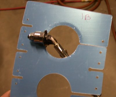
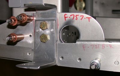 When I made the hole in
the F757-T, it was at the same time I was doing the finger access holes for
the cabin frame F631As. Van's had told me the exact
size/shape/location of the holes was not critical, as it was just to get my
fingers in there. So, I assumed the square hole in the F757 was for
the same reason, so I didn't bother with a square hole; I just drilled out a
1" round hole. It turns out this hole is for the canopy
lock finger to pass through. I just wanted to confirm with Van's that
the shape of the hole wouldn't cause any problems. Bruce said it did
not. I was tempted to swap then out for new ones, but I guess it
really doesn't matter.
When I made the hole in
the F757-T, it was at the same time I was doing the finger access holes for
the cabin frame F631As. Van's had told me the exact
size/shape/location of the holes was not critical, as it was just to get my
fingers in there. So, I assumed the square hole in the F757 was for
the same reason, so I didn't bother with a square hole; I just drilled out a
1" round hole. It turns out this hole is for the canopy
lock finger to pass through. I just wanted to confirm with Van's that
the shape of the hole wouldn't cause any problems. Bruce said it did
not. I was tempted to swap then out for new ones, but I guess it
really doesn't matter.
Aug 26 - Started the day by calling Van's yet again. Gus said I'll need to use a canopy cover over the hinge slots. I had worried about what was going to keep the water out of there. I still am. I'll probably end up making some sort of waterproof cover to go between the open canopy hinge slot and the expensive avionics. I can seal the subpanel flange gaps with ProSeal, but the hinge gap has to stay open, so the hinge will swing through it. Gus also said the C702 skin should be FLUSH, not overhanging the fuselage side skin, and the aft part of the WD716 weldment should be UP some, not sitting on the fuselage deck. I also got some tips and answers from the RV7 list, after an overnight delay. Dan said he'd go with a skin overhang another time. I think the only way you could do that is by custom making your own, wider C702 skin. Also spent a bunch of time on avionics stuff. I also received the air cleco tool I got from Jeff, another RV builder. That should help a lot with taking these skins on and off about a million times in the fitting of this canopy, and it aggravating carpal tunnel pain in my hands. Finally got back to the canopy frame in late afternoon. First, I blocked up the aft part of the canopy frame. This made a HUGE difference in the fit. Now the skin fits about right, EXCEPT (grrrrr) that now there is too much gap at the bottoms, where Van's suggested I file some off to improve the fit. There is no need for any gap at all on the bottoms, as the skin here swings AFT when teh canopy is opened. If I hadn't filed that off, it'd be perfect now. The width of the bottom gaps is now just about exactly the same amount as what I filed off. I can either accept it as is, and fill the gap in with ProSeal when I seal the subpanel flange gaps, or I can order a new C702. I decided to do the former. I drilled & clecoed the C614 splice plate to the WD716 canopy frame weldment. The directions said to drill to #40 now and adjust with #30 later, but, just like Dan did, I already drilled them to #30, cuz that's what it said on the PLANS. Maybe putting a note on the plans would be a great idea! Then I noticed that, at the center of the top of the canopy frame, the C702 is slightly below the fuse top skin. If anything, it needs to be slightly above it, so the 702 skin will clear the 771 skin when the frame is tipped up. So, I took the clecoes out of one side of the C614 splice plate and pushed it up in the middle (this is with the frame off the fuselage; it doesn't move either way when the hinges are in) so the outside holes are off alignment by 1/2 rivet diameter. I clamped it like that, drilled a hole, clecoed it, and put the frame hinges back in the hinge blocks. See pic below for more details. Drilled and clecoed the frame hinge gusset brackets. Everything looked good to go at that point, so I clecoed everything together, put the frame on, and pulled it in as tight as I could. Then I start-drilled the 1/4" holes through the hinge blocks and into the hinge arms. When I removed the canopy frame to see where the drill marks were on the hinge arms, it was exactly like what Dan got; the RT one was perfectly centered. The left one was way to the aft. I was going to call Van's to confirm the frame aluminum is 6061 and can be welded, but then I realized, duh, of course it's 6061 - it's already TIG welded. So, in the morning, I will use my new TIG welder and put some material on the aft side of that LT hinge arm. I also filed the canopy fwd seal lip back some, and deburred the edge. Also took this opportunity to drill out the rivets holding the F697 in, as I will not be using any of the canopy eject hardware. 7.0 hr
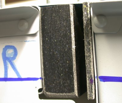
![]() Put a spacer under the
aft part of the weldment, so it isn't sitting all the way down on the
F721. It is not supposed to be all the way down on the fuselage rail,
and the C702 canopy skin is supposed to be flush with, but not overlapping,
the fuselage skin. NOTE: this turned out to be one of the
keys to my fit problem.
Put a spacer under the
aft part of the weldment, so it isn't sitting all the way down on the
F721. It is not supposed to be all the way down on the fuselage rail,
and the C702 canopy skin is supposed to be flush with, but not overlapping,
the fuselage skin. NOTE: this turned out to be one of the
keys to my fit problem.
 Now it fits pretty darn
good, after all the above steps. It's less than a 1/16" gap at
the top. Note, however, that the bottom edge, now that I have the
canopy frame sitting about 1/8" up above the fuselage deck, has too
much gap. There are 2 problems with this. For one thing, either
the gap should be equal all the way across, for appearance sake, or it
should be a slight gap at the top and none at the bottom. This is
because you need a slight gap at the top, because, from the 45 degree point
along the curve and up, the skin will move forward as the canopy frame is
tipped up. From the 45 degree point down , the edge will move BACK as
the canopy frame is tipped up. This is due to the geometry of the
hinge, the canopy frame, and the curve. Second, the gap you see at the
bottom is exactly what I filed off the edge of this skin, when Van's told me
to go ahead and file it to fit, and when the real cause was because I had
the aft portion of the weldment sitting down on the fuselage deck, instead
of being shimmed up about 1/8"-3/16". This is the LT side.
Now it fits pretty darn
good, after all the above steps. It's less than a 1/16" gap at
the top. Note, however, that the bottom edge, now that I have the
canopy frame sitting about 1/8" up above the fuselage deck, has too
much gap. There are 2 problems with this. For one thing, either
the gap should be equal all the way across, for appearance sake, or it
should be a slight gap at the top and none at the bottom. This is
because you need a slight gap at the top, because, from the 45 degree point
along the curve and up, the skin will move forward as the canopy frame is
tipped up. From the 45 degree point down , the edge will move BACK as
the canopy frame is tipped up. This is due to the geometry of the
hinge, the canopy frame, and the curve. Second, the gap you see at the
bottom is exactly what I filed off the edge of this skin, when Van's told me
to go ahead and file it to fit, and when the real cause was because I had
the aft portion of the weldment sitting down on the fuselage deck, instead
of being shimmed up about 1/8"-3/16". This is the LT side.
 It's the same on the RT,
where the bottom end gap is a bit less, and where I filed a bit les off the
skin. Again, it looks like the same amount I filed off. It's
very tempting to order a new C702 skin and start over with it, now that I
have the rest of the canopy fwd frame set up right. I decided to fill
the gap with ProSeal when I seal the gaps between the subpanel flange
sections.
It's the same on the RT,
where the bottom end gap is a bit less, and where I filed a bit les off the
skin. Again, it looks like the same amount I filed off. It's
very tempting to order a new C702 skin and start over with it, now that I
have the rest of the canopy fwd frame set up right. I decided to fill
the gap with ProSeal when I seal the gaps between the subpanel flange
sections.
 The one thing I can't get
rid of, and Dan says he never got
rid of it, is where the curve of the C702 canopy frame fwd skin bows up
higher than the F771 fwd fuselage skin, even though the skins are flush at
the top and along the sides/bottoms.
The one thing I can't get
rid of, and Dan says he never got
rid of it, is where the curve of the C702 canopy frame fwd skin bows up
higher than the F771 fwd fuselage skin, even though the skins are flush at
the top and along the sides/bottoms.
 This pic may be a bit
confusing, because of the reflection. The upper 2 rows of clecoes
shown here is actually a reflection in the shiny C702 skin. Once I got
the canopy frame weldment and the C702 canopy skin as close as I could get
them to being right, I drilled and clecoed the C614 canopy frame splice
plate in place. As Dan
reported on his site, they tell you on the drawing to drill these holes to
1/8", then later in the manual, they tell you to only drill to
3/32" at first. It didn't seem to make much difference, though,
as the frame is quite stiff at this point, and there's no movement in the 2
halves of the fwd channel now, anyway.
This pic may be a bit
confusing, because of the reflection. The upper 2 rows of clecoes
shown here is actually a reflection in the shiny C702 skin. Once I got
the canopy frame weldment and the C702 canopy skin as close as I could get
them to being right, I drilled and clecoed the C614 canopy frame splice
plate in place. As Dan
reported on his site, they tell you on the drawing to drill these holes to
1/8", then later in the manual, they tell you to only drill to
3/32" at first. It didn't seem to make much difference, though,
as the frame is quite stiff at this point, and there's no movement in the 2
halves of the fwd channel now, anyway.
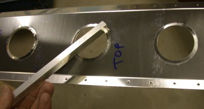
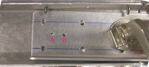 This shows where I tried to
modify the curve of the top of the fwd channel on the canopy frame
weldment. The 1/8" holes show where I drilled this in
place. There was no vertical movement available to me to adjust any of
this. However, I was disturbed by the fact that the canopy frame fwd
channel tends to sink down in the middle. This is the opposite of what
you need for problem-free opening of the canopy. If you can get the
C70s skin to
sit a bit higher in the middle (between the hinges) than the F771 skin, you will be MUCH better off. So,
with the frame removed from the plane and the C702 skin removed from the
frame, I tried experimenting with moving the hole alignments. First, I
pushed the center up so the left-most holes in this pic were misaligned by
1/2 hole. I then clamped it and drilled the 3/32" hole you see
at "A" in the middle. Then I clecoed that hole and put the frame back in the
plane. It didn't seem to make much difference, so I pushed the joint
up further, so the LT holes were off by an entire hole. I drilled hole
"B" and tried
that. It didn't seem to help much with making the middle bow up some,
but it did draw the sides in so they no longer fit well. So, I went
back to the original 1/8" holes & left it there.
This shows where I tried to
modify the curve of the top of the fwd channel on the canopy frame
weldment. The 1/8" holes show where I drilled this in
place. There was no vertical movement available to me to adjust any of
this. However, I was disturbed by the fact that the canopy frame fwd
channel tends to sink down in the middle. This is the opposite of what
you need for problem-free opening of the canopy. If you can get the
C70s skin to
sit a bit higher in the middle (between the hinges) than the F771 skin, you will be MUCH better off. So,
with the frame removed from the plane and the C702 skin removed from the
frame, I tried experimenting with moving the hole alignments. First, I
pushed the center up so the left-most holes in this pic were misaligned by
1/2 hole. I then clamped it and drilled the 3/32" hole you see
at "A" in the middle. Then I clecoed that hole and put the frame back in the
plane. It didn't seem to make much difference, so I pushed the joint
up further, so the LT holes were off by an entire hole. I drilled hole
"B" and tried
that. It didn't seem to help much with making the middle bow up some,
but it did draw the sides in so they no longer fit well. So, I went
back to the original 1/8" holes & left it there.
 After finally
getting everything aligned properly, I was ready to mark and drill the
canopy frame hinge arms. Again, just as Dan
reported on his site, the RT one came out perfectly centered, but the LT one
is way aft, too near the edge. This mark is only 0.222" from the
aft edge. Drilling a 3/8" hole centered here will leave almost no
edge at all (0.034")on the aft side (LT in this pic). I think Dan
kinda fudged his inward, but I want my hinge bolt hole to go exactly where
it needs to go; not a compromise. I decided to use the new TIG welder,
and add material to the aft side of this hinge arm.
After finally
getting everything aligned properly, I was ready to mark and drill the
canopy frame hinge arms. Again, just as Dan
reported on his site, the RT one came out perfectly centered, but the LT one
is way aft, too near the edge. This mark is only 0.222" from the
aft edge. Drilling a 3/8" hole centered here will leave almost no
edge at all (0.034")on the aft side (LT in this pic). I think Dan
kinda fudged his inward, but I want my hinge bolt hole to go exactly where
it needs to go; not a compromise. I decided to use the new TIG welder,
and add material to the aft side of this hinge arm.
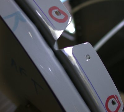
 Dan thought maybe
he'd drilled his 1/4" hole (for the hinge pivot pins/bolts)
wrong. As you can see in this pic and the next one, the holes are
exactly the same distance fwd/aft of the flange on the center subpanel.
This pic is the RT side. The blue marks on the F771 skin above are
where I outlined where the rib flange edges are. I'll need to know
this when I go to start laying out my custom avionics access panels in the
F771 skin.
Dan thought maybe
he'd drilled his 1/4" hole (for the hinge pivot pins/bolts)
wrong. As you can see in this pic and the next one, the holes are
exactly the same distance fwd/aft of the flange on the center subpanel.
This pic is the RT side. The blue marks on the F771 skin above are
where I outlined where the rib flange edges are. I'll need to know
this when I go to start laying out my custom avionics access panels in the
F771 skin.
 And this one is
the LT side. Right at the edge of the flange on both sides. I
wonder if there's a problem with the weldment jigging, although Walter
did not report this problem.
And this one is
the LT side. Right at the edge of the flange on both sides. I
wonder if there's a problem with the weldment jigging, although Walter
did not report this problem.
Aug 27 - spent the morning on numerous phone calls and emails related to avionics. Did some TIG practice to get warmed up, then went into town to get a new liner for my aluminum MIG welder. 1.5 hr
Aug 28 -did some more TIG practice, then welded up the aft edge of the LT hinge arm. Filed off the excess metal off the side of the hinge arm. Drilled out the RT hinge arm. It went horribly. The air drill was too fast, and I got terrible bit chatter. It made a quite misshapen hole with the bit chatter, but I only went partway through . I drilled the rest of the hole OK with an electric drill. I will be very surprised and lucky if the hole center hasn't moved through all that. Put the canopy frame in, and was amazed that the RT hinge bushing seems to be in the right place. Marked the LT drill point for the hinge bolt. Tried to drill it all in place, but having problems with that, so I removed the fame and drilled the LT hinge arm. Received Avery order and EcuTek CD. 3.5 hr
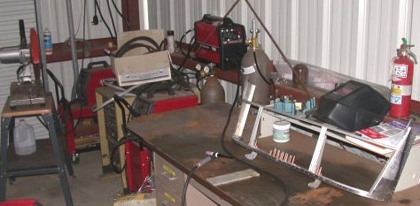 This is the
"welding corner", and I am getting ready to TIG weld the
canopy frame LT hinge arm.
This is the
"welding corner", and I am getting ready to TIG weld the
canopy frame LT hinge arm.
 Here, I have welded
more material to the aft side of the hinge arm.
Here, I have welded
more material to the aft side of the hinge arm.
 I drilled the
RT arm to 1/4" first. When I tried to open it to 11/32", the
*&^@$ bit started chattering like crazy and chewed the top of the hole
all up. I was drilling too fast, with the air drill. I
stopped right away, before going too deep like that, switched over to an
electric drill, and finished it OK. Then I reamed the hole to
3/8". This is the inner view of the RT hinge arm. I figured
it would be a complete miracle if the hole center didn't get moved with all
that chattering going on. But I put the bushing in and decided to try
it. It actually fit perfectly the first time. A true miracle!
I drilled the
RT arm to 1/4" first. When I tried to open it to 11/32", the
*&^@$ bit started chattering like crazy and chewed the top of the hole
all up. I was drilling too fast, with the air drill. I
stopped right away, before going too deep like that, switched over to an
electric drill, and finished it OK. Then I reamed the hole to
3/8". This is the inner view of the RT hinge arm. I figured
it would be a complete miracle if the hole center didn't get moved with all
that chattering going on. But I put the bushing in and decided to try
it. It actually fit perfectly the first time. A true miracle!
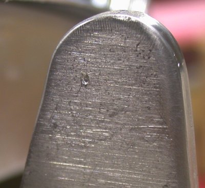
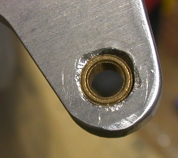
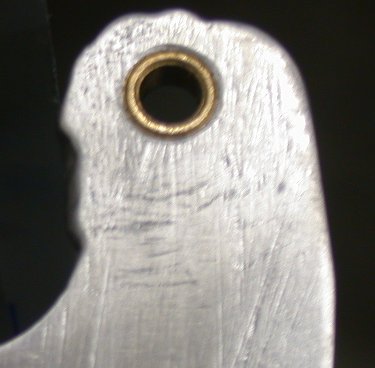
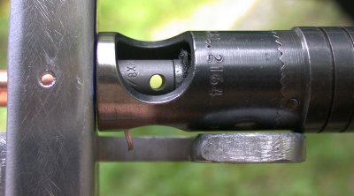
 This is the
outer view of the RT hinge arm. The hole was true on this side.
The bushing is a very light press fit (just a bit more than can be done with
fingers). I used the rivet squeezer with flat rivet sets to squeeze it
in there. It wasn't as tight as I would have liked. When I am
sure it's where I want it, I will lock it in there with LocTite Red.
This is the
outer view of the RT hinge arm. The hole was true on this side.
The bushing is a very light press fit (just a bit more than can be done with
fingers). I used the rivet squeezer with flat rivet sets to squeeze it
in there. It wasn't as tight as I would have liked. When I am
sure it's where I want it, I will lock it in there with LocTite Red.
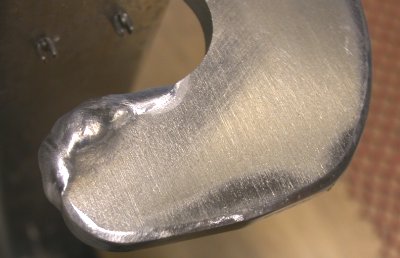
 here's the LT
hinge arm, with the aft edge welded up with more material to surround the
bushing, then filed flat.
here's the LT
hinge arm, with the aft edge welded up with more material to surround the
bushing, then filed flat.
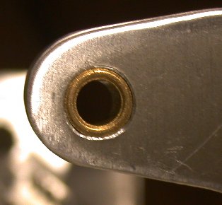
 Here is the LT
hinge arm, with the bushing pressed in. View looking outboard.
Here is the LT
hinge arm, with the bushing pressed in. View looking outboard.
Aug 30 - After putting the frame back in with the bushing in both sides, the bolt will not go through the LT hinge bushing. Looked under the F771 skin to see what is the problem. Found the hole is not in the right place. Marked where it should be, removed frame, and welded up the bushing hole to move the hinge bolt hole about 1/8". Moving the bushing hole worked nicely, and the bolt goes in nicely now. Now the canopy seal flange lip rubs against the canopy frame, so I filed the lip until I had no scraping as I raised the canopy frame. The clecoes were getting in the way of working on the seal flange lip clearance, so I decided to rivet the frame together. See pic notes on how I had to tweak the rivet installation on the fame center to get the sag out of it. Finally got it so the frame would swing up without scraping on the seal flange lip. Then added the C702 skin. The 702 skin was not fitting correctly on the LT side. It looks like the fore/aft connecting bar got pulled in a bit when I riveted the hinge gussets, so either the connecting bar rivet hole will align or the LT skin rivet holes will align, but not both. Screwed with that awhile, then redrilled the LT fwd skin holes, as this tends to push the skin slightly fwd, which is good. Finally decided to order new C702 skin. Received ACS order; mostly aluminum sheets for doing custom access panels. Cleaned up bench. 9.5 hr
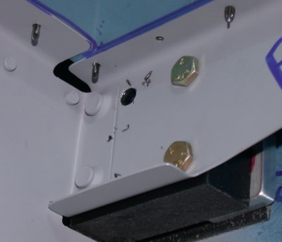
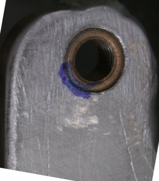
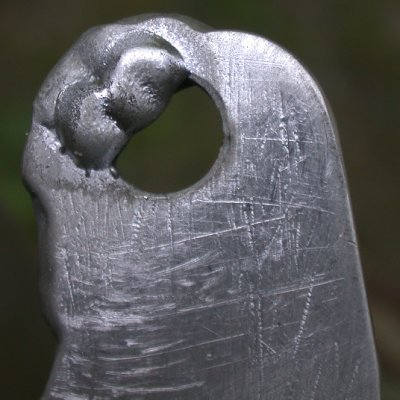
 This is the view
from the outboard side of the F745, showing how the LT hinge bolt doesn't
want to go through. I took a blue pen and stuck it in the hole at the
7-8 o'clock position, to mark the location and distance that the bushing is
off. Also note the use of temporary hardware store non-locking nuts on
the 2 bolts for the hinge blocks. I can spin them on and off quickly
and easily with my fingers, while doing setups and layouts, and without
wearing out the nylon in the locknuts. When I am done fiddling with
this, and ready to put it together for the final time, the nuts will be the
proper locknuts. I used this technique throughout the plane.
This is the view
from the outboard side of the F745, showing how the LT hinge bolt doesn't
want to go through. I took a blue pen and stuck it in the hole at the
7-8 o'clock position, to mark the location and distance that the bushing is
off. Also note the use of temporary hardware store non-locking nuts on
the 2 bolts for the hinge blocks. I can spin them on and off quickly
and easily with my fingers, while doing setups and layouts, and without
wearing out the nylon in the locknuts. When I am done fiddling with
this, and ready to put it together for the final time, the nuts will be the
proper locknuts. I used this technique throughout the plane.
 Here's the same
view of the outboard portion of the LT canopy hinge arm, showing where I
marked it through the hole in the previous picture. This shows the
direction and amount that the hole needs to be moved. The bushing
looks elongated, but it isn't; I think it's because I rotated the image.
Here's the same
view of the outboard portion of the LT canopy hinge arm, showing where I
marked it through the hole in the previous picture. This shows the
direction and amount that the hole needs to be moved. The bushing
looks elongated, but it isn't; I think it's because I rotated the image.
 This pic is
taken from the opposite side of where the previous pic was taken from.
This is after I removed the bushing and used the TIG welder to add some
material to the side of the hole that was opposite the blue marks in the
previous picture. I could have wrapped the weld around the hole more,
but it would have made it harder to visualize where the original hole
was. I didn't want to lose track of that. I just wanted to do
this correction ONCE, not screw with it for days. No pic of it, but
the next step was to use a small carbide cutter in the side of the hole
directly opposite the weld. When I had it nearly 3/8" from center
of weld to center of new ground-out area, I started with a 11/32"
drill, then used a 3/8" reamer to bring it up to final size, without
moving the hole center from where I wanted it. Then I filed the
surface flat again. I knew the widest points of the existing hole,
along the axis between center of the weld and the center of the ground-out
area, shown here at the 1 o'clock and 8 o'clock positions, would be too
wide, as they would no longer be the center of the hole, but I left them
this way for tighter control of where the hole was being moved to.
More welding on the hole would have made it hard to know where the original
hole was. If the piece was by itself, I could have chucked it up the
mill and moved it precisely, but this hand method worked fine.
This pic is
taken from the opposite side of where the previous pic was taken from.
This is after I removed the bushing and used the TIG welder to add some
material to the side of the hole that was opposite the blue marks in the
previous picture. I could have wrapped the weld around the hole more,
but it would have made it harder to visualize where the original hole
was. I didn't want to lose track of that. I just wanted to do
this correction ONCE, not screw with it for days. No pic of it, but
the next step was to use a small carbide cutter in the side of the hole
directly opposite the weld. When I had it nearly 3/8" from center
of weld to center of new ground-out area, I started with a 11/32"
drill, then used a 3/8" reamer to bring it up to final size, without
moving the hole center from where I wanted it. Then I filed the
surface flat again. I knew the widest points of the existing hole,
along the axis between center of the weld and the center of the ground-out
area, shown here at the 1 o'clock and 8 o'clock positions, would be too
wide, as they would no longer be the center of the hole, but I left them
this way for tighter control of where the hole was being moved to.
More welding on the hole would have made it hard to know where the original
hole was. If the piece was by itself, I could have chucked it up the
mill and moved it precisely, but this hand method worked fine.
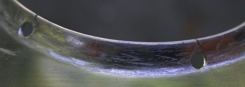
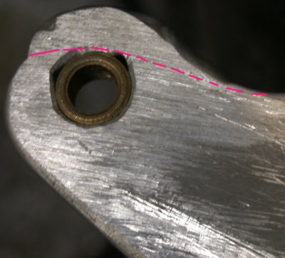 The red
dotted line shows approximately where the original edge was. The dark
triangles at 2 o'clock and 10 o'clock around the bushing in this pic show
the 2 wide points in the original hole, as described with the previous
pic. They are essentially triangular holes that go all the way
through. Now that I have the hole located, I could go back & weld
up those little triangles. I could also just ignore them, as the
aluminum is just holding the bushing here, and it's at least as tight a fit
as the RT side. What I decided was the simplest action was to just
lock the bushing in with LocTite Red (high strength stud & bearing
lock). If I want to go even further, I can just mix up some JB Weld
and pour it into the 2 triangular holes. The bushing sure isn't going
anywhere. Oh, and BTW, when I put the hinges back into the hinge
blocks, both LT & RT hinge bolts slid through snugly. So, that's
all set. I just need to get some LocTite Red, and I'll be all set.
The red
dotted line shows approximately where the original edge was. The dark
triangles at 2 o'clock and 10 o'clock around the bushing in this pic show
the 2 wide points in the original hole, as described with the previous
pic. They are essentially triangular holes that go all the way
through. Now that I have the hole located, I could go back & weld
up those little triangles. I could also just ignore them, as the
aluminum is just holding the bushing here, and it's at least as tight a fit
as the RT side. What I decided was the simplest action was to just
lock the bushing in with LocTite Red (high strength stud & bearing
lock). If I want to go even further, I can just mix up some JB Weld
and pour it into the 2 triangular holes. The bushing sure isn't going
anywhere. Oh, and BTW, when I put the hinges back into the hinge
blocks, both LT & RT hinge bolts slid through snugly. So, that's
all set. I just need to get some LocTite Red, and I'll be all set.
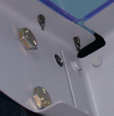
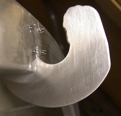
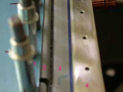 OK, now
that I finally got the damn canopy frame hinges located right where I wanted
them, it was time to try tipping the canopy up. Of course, it won't
tip up. That's because you have to trim the edge of the canopy seal
flange that's riveted to the subpanel. It especially needs it in the
center, where the frame moves fwd as it tips up. #1 is the F771 fwd
fuselage skin, #2 is the subpanel, #3 is the canopy seal flange, and #4 is
the canopy frame fwd channel.
OK, now
that I finally got the damn canopy frame hinges located right where I wanted
them, it was time to try tipping the canopy up. Of course, it won't
tip up. That's because you have to trim the edge of the canopy seal
flange that's riveted to the subpanel. It especially needs it in the
center, where the frame moves fwd as it tips up. #1 is the F771 fwd
fuselage skin, #2 is the subpanel, #3 is the canopy seal flange, and #4 is
the canopy frame fwd channel.
 For some
earlier project, I ground the foot off one of my countersink cages for
access into tight places. Actually, a narrow body one (like here)
would have worked, even with a foot. Anyway, no "suicide
mode" here. Here, i am countersinking the canopy hinge gusset
plate rivet holes.
For some
earlier project, I ground the foot off one of my countersink cages for
access into tight places. Actually, a narrow body one (like here)
would have worked, even with a foot. Anyway, no "suicide
mode" here. Here, i am countersinking the canopy hinge gusset
plate rivet holes.
 Here is the
fwd channel of the WD716 canopy frame weldment, all riveted together with
the C614 splice plate. I mentioned earlier that I'd tried to force the
middle here up some, then abandoned the effort. As I started to rivet
this, it clearly had a sag in the middle, and I just knew I'd pay for it big
time later on if I didn't bite the bullet and force a fix now. NOTE -
when you're building this, you'll see the frame has a tendency to sag in the
middle. Due to how the canopy opens, it needs to be flat or even
curving up a bit in the center, so the C702 skin will clear the F771 skin in
the middle as it moves fwd. If you don't fight that sagging tendency
all the way through building this, your canopy will be harder to get open,
and you'll have to resort to shimming the C702 skin up to clear the
F771. I already had put in 4 rivets in the RT side (in this pic),
so I drilled out the 3 I had done on the LT side, and forced the middle
up. Of course, that put the rivet holes out of alignment, but I
decided that was the least of my worries at this point. I made sure
the top surfaces remained flush, and pushed the middle up so the rivet holes
were out of alignment by about 1/2 hole on the fat LT in this pic.
Then I clamped it in place. Of course, by then it was already
countersunk, and I didn't want to mess with the countersinks (for good rivet
flush seating). So, I put a 1/16" end mill into the drill and
used it to manually move the backing plate hole down to match where the
countersink hole was. You can't just stick a drill bit in there and
try that, because the drill bit would rather eat through the thinner
countersink edge than the full thickness of the backing plate. Then I
trued up the hole with a 1/8" bit and used -6 rivets instead of the -5
the plans called for. That's because the rivet will fill up the hole,
which is why I wasn't worried about the hole being elongated, but it will
end up too short if you use the "correct" length, because all the
length gets used up as width when the rivet material fills the hole.
If you're driving rivets, you won't get away with this (unless you're a hell
of a lot better at it than I am), cuz they'll bend over, but I did it with
the pneumatic squeezer, and it came out fine. The LT 2 holes (on the
LT side) were elongated by 1/16". The middle 2 were elongated by
1/32". The RT ones (on the LT half) were hardly elongated at
all. Then I added another rivet to the center, just to make up for any
possible weakness caused by the elongated holes. I'd have done 2 in
the center, but the tooling hole was right in the way for the other one.
Here is the
fwd channel of the WD716 canopy frame weldment, all riveted together with
the C614 splice plate. I mentioned earlier that I'd tried to force the
middle here up some, then abandoned the effort. As I started to rivet
this, it clearly had a sag in the middle, and I just knew I'd pay for it big
time later on if I didn't bite the bullet and force a fix now. NOTE -
when you're building this, you'll see the frame has a tendency to sag in the
middle. Due to how the canopy opens, it needs to be flat or even
curving up a bit in the center, so the C702 skin will clear the F771 skin in
the middle as it moves fwd. If you don't fight that sagging tendency
all the way through building this, your canopy will be harder to get open,
and you'll have to resort to shimming the C702 skin up to clear the
F771. I already had put in 4 rivets in the RT side (in this pic),
so I drilled out the 3 I had done on the LT side, and forced the middle
up. Of course, that put the rivet holes out of alignment, but I
decided that was the least of my worries at this point. I made sure
the top surfaces remained flush, and pushed the middle up so the rivet holes
were out of alignment by about 1/2 hole on the fat LT in this pic.
Then I clamped it in place. Of course, by then it was already
countersunk, and I didn't want to mess with the countersinks (for good rivet
flush seating). So, I put a 1/16" end mill into the drill and
used it to manually move the backing plate hole down to match where the
countersink hole was. You can't just stick a drill bit in there and
try that, because the drill bit would rather eat through the thinner
countersink edge than the full thickness of the backing plate. Then I
trued up the hole with a 1/8" bit and used -6 rivets instead of the -5
the plans called for. That's because the rivet will fill up the hole,
which is why I wasn't worried about the hole being elongated, but it will
end up too short if you use the "correct" length, because all the
length gets used up as width when the rivet material fills the hole.
If you're driving rivets, you won't get away with this (unless you're a hell
of a lot better at it than I am), cuz they'll bend over, but I did it with
the pneumatic squeezer, and it came out fine. The LT 2 holes (on the
LT side) were elongated by 1/16". The middle 2 were elongated by
1/32". The RT ones (on the LT half) were hardly elongated at
all. Then I added another rivet to the center, just to make up for any
possible weakness caused by the elongated holes. I'd have done 2 in
the center, but the tooling hole was right in the way for the other one.
Aug 31 - more bench cleanup. Fabricated wing tiedown eyebolt holder. Make spacer blocks for F631As for aft part of canopy frame. Make new C704. Drill & cleco new C704. Bend upper flange of F631As so they're a bit more than 90 degrees. 6.5 hr
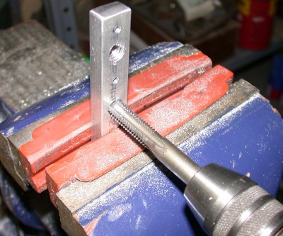 Here, I
am tapping the holes for the custom holder for the wing and tail tiedown
eyebolts. I don't want them out in the airstream while I'm flying, and
I don't want them bouncing around the inside of the cabin, either. So
I made this block out of 3/8" bar stock to hold them.
Here, I
am tapping the holes for the custom holder for the wing and tail tiedown
eyebolts. I don't want them out in the airstream while I'm flying, and
I don't want them bouncing around the inside of the cabin, either. So
I made this block out of 3/8" bar stock to hold them.
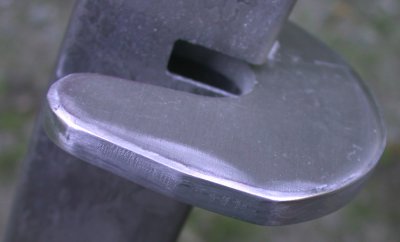
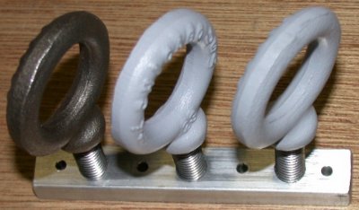 Here is
the finished holder for the tiedown bolts. I will rivet it in place
somewhere; maybe behind the passenger seat. I primed the 2 wing
tiedowns, but not the tail tiedown yet. I had to get that as a
separate order, cuz Van's catalog says you need 2, and so I ordered 2.
Later, I realized I'd need a third one for the tail. They're as close
together as I can get them and still be able to screw them in and out.
Here is
the finished holder for the tiedown bolts. I will rivet it in place
somewhere; maybe behind the passenger seat. I primed the 2 wing
tiedowns, but not the tail tiedown yet. I had to get that as a
separate order, cuz Van's catalog says you need 2, and so I ordered 2.
Later, I realized I'd need a third one for the tail. They're as close
together as I can get them and still be able to screw them in and out.
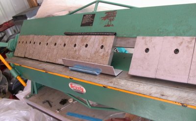
![]() Planing some
scrap 1" cherry lumber for the 7/8" spacers between the canopy
frame F631As and the cabin frame. Dan Checkoway said he found that
13/16" works better, so it was very easy to just run a second piece
through the planer a couple more passes until I had a set of 7/8" and a
set of 13/16" blocks. We have a very small factory in town that
makes custom cabinet doors, so they sell a grain bag full of scraps like
this for a buck. People here use it for kindling, and occasionally for
small projects. The planer is yet another Grizzly
tool. Back in about 2000-2002, I was a VERY good Grizzly customer.
Planing some
scrap 1" cherry lumber for the 7/8" spacers between the canopy
frame F631As and the cabin frame. Dan Checkoway said he found that
13/16" works better, so it was very easy to just run a second piece
through the planer a couple more passes until I had a set of 7/8" and a
set of 13/16" blocks. We have a very small factory in town that
makes custom cabinet doors, so they sell a grain bag full of scraps like
this for a buck. People here use it for kindling, and occasionally for
small projects. The planer is yet another Grizzly
tool. Back in about 2000-2002, I was a VERY good Grizzly customer.
![]() Then rip 'em
for width
Then rip 'em
for width
![]() Then chop 'em
for length
Then chop 'em
for length
![]() I used the shear
to chop off the 4 pieces of 1/8"x1"x2" I need for canopy
frame temp layout spacers.
I used the shear
to chop off the 4 pieces of 1/8"x1"x2" I need for canopy
frame temp layout spacers.
![]() And this is what I
ended up with for spacers to lay out the aft part of the canopy frame.
I made a full set of the 7/8" the plans called for, and a full set of
13/16" that Dan said he had to use.
And this is what I
ended up with for spacers to lay out the aft part of the canopy frame.
I made a full set of the 7/8" the plans called for, and a full set of
13/16" that Dan said he had to use.
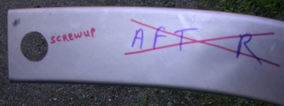 I didn't mention it
back when I was doing the F631As for the cabin frame, but I drilled one of
those bolt/nut access holes on the WRONG END of one of the F631A pieces, so
I just set it aside, as I had 6 pieces at that time, and only needed
4. Well, here I am back to it. I will need to fabricate a longer
C704 splice plate to go over the hole and further down the channel than the
stock C704 does. After I get this all put together, I will fill this
hole in with a scrap piece of aluminum and some JB Weld.
I didn't mention it
back when I was doing the F631As for the cabin frame, but I drilled one of
those bolt/nut access holes on the WRONG END of one of the F631A pieces, so
I just set it aside, as I had 6 pieces at that time, and only needed
4. Well, here I am back to it. I will need to fabricate a longer
C704 splice plate to go over the hole and further down the channel than the
stock C704 does. After I get this all put together, I will fill this
hole in with a scrap piece of aluminum and some JB Weld.
 I used my A&P
friend Jim's idea to make it quick and
easy to bend the flange on that new custom C704 splice plate I had to build
to fix the earlier screwup, back when I was building the cabin frame, on one
of the F631As.
I used my A&P
friend Jim's idea to make it quick and
easy to bend the flange on that new custom C704 splice plate I had to build
to fix the earlier screwup, back when I was building the cabin frame, on one
of the F631As.
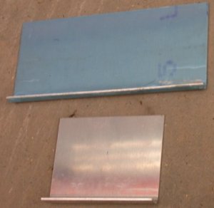 As you can see here, the new
C704, in blue, is nearly twice as long as the stock piece. I
made it from 0.063" 2024T3 plate I had laying around after building the
autopilot servo mounts.
As you can see here, the new
C704, in blue, is nearly twice as long as the stock piece. I
made it from 0.063" 2024T3 plate I had laying around after building the
autopilot servo mounts.
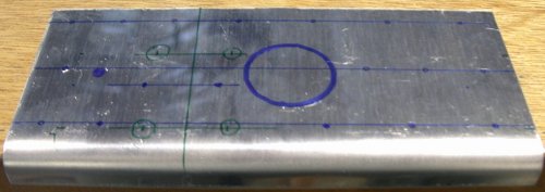 Here's the rivet layout I
used with the new C704 plate. The first thing I did was mark the large
hole, the tooling hole, and the bolt holes (in green) on it, then I laid out
my rivet pattern around the holes. I didn't get too wrapped up in the
rivet locations specified in the plans. When the plans specify a
location in /32", I assume value of the number under the line (is that
the numerator or denomminator?) is the tolerance to use. If they say
11/32", I assume that must mean exactly 11/32", not 10 and not
12. Anyway, I see no reason why exact locations matter, so I just used
the same edge distance they did, then laid out the rivets where they seemed
good to go.
Here's the rivet layout I
used with the new C704 plate. The first thing I did was mark the large
hole, the tooling hole, and the bolt holes (in green) on it, then I laid out
my rivet pattern around the holes. I didn't get too wrapped up in the
rivet locations specified in the plans. When the plans specify a
location in /32", I assume value of the number under the line (is that
the numerator or denomminator?) is the tolerance to use. If they say
11/32", I assume that must mean exactly 11/32", not 10 and not
12. Anyway, I see no reason why exact locations matter, so I just used
the same edge distance they did, then laid out the rivets where they seemed
good to go.
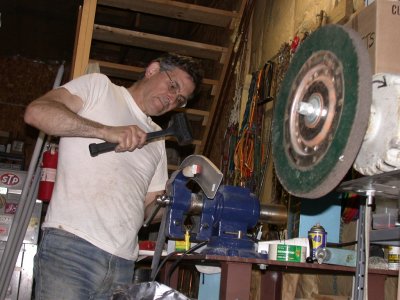 The FAA likes
pictures with ME in them, so here's one of me using a rubber dead blow
hammer to increase the angle of the top flange on the F631A ribs that go at
the back of the tipup canopy. They come with an angle slightly less
than 90 degrees, and it needs to be bent a bit more to a little more than 90
degrees. I was using the hand seaming tool, but it doesn't work on the
curved part, and this hammer worked very well. The manual said to bend
the flanges, but they didn't say which ones. I am fairly sure they
meant just the top flange needs it, where the canopy plexi will sit.
The FAA likes
pictures with ME in them, so here's one of me using a rubber dead blow
hammer to increase the angle of the top flange on the F631A ribs that go at
the back of the tipup canopy. They come with an angle slightly less
than 90 degrees, and it needs to be bent a bit more to a little more than 90
degrees. I was using the hand seaming tool, but it doesn't work on the
curved part, and this hammer worked very well. The manual said to bend
the flanges, but they didn't say which ones. I am fairly sure they
meant just the top flange needs it, where the canopy plexi will sit.
 I started out with pretty
straight F631As. After hammering the top flanges to a new angle, they
were warped as hell.
I started out with pretty
straight F631As. After hammering the top flanges to a new angle, they
were warped as hell.
BACK TO MY RV BUILDER'S HOME
BACK TO BRIAN'S HOME