June 5 - I used a system of
adjustable motorcycle tiedown straps, connected with rock climbing slings
and carabiners, to pick up the engine and crate, then rotate the engine 90
degrees, so it was in proper level mounting position. Used the tractor
to take the engine over to the garage, and transferred the engine from the
tractor loader bucket to the engine crane. Everything went very
smoothly, as planned. I had already spent some time thinking and
planning how I'd safely flip the engine without letting the bottom of it
(with the exhaust pipes hanging out) touch the ground. Adjusted the
mount on the engine crane a couple times, and used the tiedown straps to
adjust the engine so it was hanging level, both side-to-side and
front-to-back. Cleaned out nose gear tubing with a 1" sandpaper drum
on my drill, so nose gear leg would
slide in. Removed the pallet from the engine frame. Redid the 2
aft slings so they were not interfering with the upper mount bolts.
2.75 hr
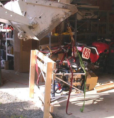
This
was taken right after I had rolled the engine and pallet up so the pallet is
standing on its edge and the engine is in its proper position. As I
gradually lifted the load and the pallet started tipping up, I kept
loosening the front tiedowns and tightening the front ones, until they were
even. I didn't take a pic of it, but I started with the pallet flat on
the ground and the front tiedowns (RT in this pic) much shorter than the
rear ones. If I'd started with them all the same length, the pallet
would have flipped to this position immediately (and quickly), possibly
striking the exhaust pipes or front of the engine on the ground & damaging
them.
Here's
a front pic of the engine, after I'd gotten it flipped over to horizontal.
The 4 motorcycle tiedowns go to an oval carabiner, which is connected with 2
rock climbing slings to 2 more 'biners, and then one 'biner is connected to
the chain on the tractor bucket. The other sling & 'biner is for
connecting to the crane.
Here, I am transferring the engine from the loader bucket to the engine
crane. This is where the second carabiner and sling come in. I
hooked the second (loose) 'biner to the crane hook, then I could lower the
bucket and transfer the weight to the crane. I ended up having to
transfer the engine back to the bucket so I could remove the crane sling
(red one), so the engine would hang higher in the crane.
These next 4 pics show the details of how I slung the engine. It
worked out very well. This is the upper RT mount. The 1/4" rock
climbing sling is thin enough that it can wrap around the mount point
without interfering with either the mount face or mount bolt. DON'T
try this with 1/4" hardware store rope! The motorcycle tiedown hooks
to the sling and to the central oval carabiner. I highly recommend the
use of motorcycle tiedowns for this, because it's so easy to control the tip
and tilt of the engine by carefully adjusting the lengths of the tiedowns.
Don't use crappy Chinese tiedowns for this! Use US-made Ancra tiedowns
rated for at least 2000 pounds each.
This is the sling holding the upper LT mount
The 2 tiedowns at the front of the engine hook directly into convenient
slots in the aluminum fwd frame plate. The bolt attaching the plate to
the tubing frame keeps the tiedown hook from moving around. In the
foreground, note the poorly made/attached aluminum vent bottle for the PSRU.
More details on that later.
This shows where all the tiedowns come together, and where I had removed the
red sling to get the engine up higher in the crane. The 4 tiedowns
hook into the oval carabiner, and the purple 'biner connects that directly
to the chain hook on the crane. By having 2 sets of 'biner & sling
above the gold oval 'biner, I can easily switch the load from crane to
tractor and back. The yellow Romex is just there to loosely hold the wiring
harness up out of the way.
Here are the engine and frame, facing each other, ready to be joined in holy
matrimony forever.
June 6 - make 1/4" to #40 adapter
sleeve, so that hole I drill for leg is perfectly centered in the pilot hole
in the engine frame as it comes from Jan. 1.0
hr
The collar on the Eggenfellner frame comes pre-drilled to about 1/4".
I wanted to make sure my pilot hole into the gear leg was perfectly
centered in the hole in the frame collar, so I made this drill bushing. The body OD is matched
to the hole in the collar, as it comes from Eggenfeller. The hole in
the bushing is
1/8". The lip gives me something to grasp and with which to remove the
bushing. Without the bushing, it's hard to make sure your gear leg
pilot hole is perfectly centered in the pilot hole in the frame. If
the leg hole isn't centered perfectly, the
leg will be rotated a bit when you start reaming both the frame hole and the
leg hole together, and the leg will no longer be perfectly vertical.
Here is the bushing in place on the collar, but not yet pushed all the way
in.
June 7 - Used digital level to
make sure engine is hanging level and gear leg is perfectly perpendicular.
Used adapter sleeve bushing to mark gear leg with 1/8" drill bit through
bushing. Mount gear leg to mill and drill it out to 1/8", then 1/4".
The drilling was much easier than expected. I was under the impression
that this leg was hardened and very difficult to drill. I had no
problems at all with it. Drilled it one more time to "M" drill size.
Used my adjustable reamer (that I bought just for this) to ream the leg and
mount together, until the threaded portion of the bolt would just barely
slide in, up to the bolt shank. That's how I reamed the holes for the
main gear legs, and it worked perfectly. The problem is that, if it's
a bit too tight when I start hammering the bolt in, I might not be able to
get it to go all the way in, and it might be difficult to get it back out,
too. It would have been EXTREMELY difficult to get back out on the
main gear legs, where I couldn't get access to the other side of the hole.
If it's too loose, well, we don't want that. So, I think it's about ready
to hammer the bolt home. The bolt that Van's supplied for this is an
AN5-20A. With the thick collar that Jan puts on his frames, I'll need
a -21A, so I ordered a couple from ACS. I also got a couple -21 bolts,
as I think a castle nut & cotter pin will be even more secure.
3.25 hr + 3.0 hr doc
Here is the nose gear leg, mounted to the mill for drilling. I made
sure the drill bit would be passing from the pilot hole I started, directly
through the center of the gear leg.
After drilling the leg and collar out to "M" drill size, I assembled the leg
into the frame, and began using my adjustable reamer to take the hole out a
few thousandths with each pass, until I could just start the bolt threads
into each hole. The threads are a few thousandths smaller than the
bolt body, so when I can just barely slip the bolt in from each end, up to
the bolt shank, I know it's ready to be pounded the rest of the way in.
The red tape tells me where the adjuster nut ended up when I did the bolt
for the main gear, so I'll know when I am getting close.
Here's the bolt, pushed in as far as I can by hand. I made sure it's
the same fit in the hole from the other end, too. Now, I'm just waiting for the
proper length bolt from ACS, and I'll drive it home. In the upper RT
corner, note one of the little instruction tags Jan puts on various parts of
the engine. They are helpful. NOTE - I finished the
job Jun 26
June 7 evening - (previous June 7 entry was
midnight to 0315) - Remove fuel line firewall union that I'd installed
earlier, according to the manual, before that location specification was
corrected.
The originally specified location is right in the way of the lower engine
frame bar. Remove the nutplates for the Lycoming aux pump; the lower
one is also interfering with that lower engine frame crossbar. Tried
lining up the engine and frame to the holes on the firewall. They
aren't even close! The upper frame holes are each at least 1/2" inside
the firewall holes. Finally smartened up and realized that the clever
way I am hoisting the engine is actually flexing the upper frame in quite a
bit, once I removed the pallet. Measured 37 1/4" between the holes in the firewall. It's 36
1/4" between the holes on the engine frame. I studied the engine,
frame, and hoist awhile, and figured out a way to hold the rear of the
engine up without pulling the upper frame arms in. I tried that, using
a ratchet tiedown as a 5th lift point, going to the housing for the upper
nose gear leg. That worked pretty well, and when the frame is relaxed
that way, it actually measures 38 1/8". I left the 2 corner tiedowns
in place loosely, so I can use them to tension the arms some at installation
time, to pull them in as needed to match the firewall holes. Also, with the strain off the upper
frame legs, I can rather easily flex the legs in and out with my arms, so I
guess that isn't nearly as stiff as I thought it was. Since I am now
1/2" outside the holes on each side, I know I can easily pull the arms in as
I need to, in order to line up the holes. It also has become apparent
to me that the frame will be in the way of doing some of the rivets that
hold the fwd fuse skin to the fuselage. Also, I think this is where
the hinges for the cowl attachment get put on. I am also trying to
figure out how & where the U720A&B, U620B,C,D pieces go, and if I need them
at all with an Eggenfellner engine. I posted a question on the
Eggenfellner list about it, but didn't get a clear answer. 3.25 hr
This firewall detail shows where I had to get the F745s and F643-1 riveted
on before mounting the engine. It also shows the 2 nutplates in the
lower center that had to be removed, and the large 3/4" hole in the lower LT
(RT in the pic) where the original plans called for placing the fuel line
bulkhead fitting. The fitting and the nutplates had to come out
because they interfere with the lower engine frame. The nutplate holes
& bad fuel line hole all need to be patched over with stainless steel. You can see the 4
engine mount holes that came pre-drilled to 1/4" as part of the QB kit.
The red dots inside the top 2 engine mount holes are where the engine frame
was lining up. Fortunately, I was able to figure out that the hoist
rig I had was pulling the frame inward. Once I released that inward
pull, the frame is actually now outside the firewall holes. So, it
will be easy to pull it in to match, just by tightening the crane hoist tiedowns. I thought I might have to remove the brake fluid reservoir,
but, for now, it's OK where it is.
Here's the new hoist method. I put a sling on the frame where the nose
gear mates, at the red arrow, then hooked a ratchet tiedown (C) from that to
the carabiner on top. Once I tightened up the ratchet tiedown to
relieve the inward pressure on the upper corners (at A and B), the frame
relaxed and will fit the firewall just fine.
June 8 - After reading emails on
the Eggenfellner site about some people's heater hookup didn't come properly
set up, I examined what I had, to see if I had the same problem. I
eventually figured out that what I have is correct, and I am supposed to cut
into the long blue hose that goes from the top RT machined tower down to the
inboard side of the water pump. Removed the radiators to send back to
Eggenfellner for fixing. Maybe I didn't mention that before, but a
couple weeks ago, Jan announced that he'd found that Niagara, the company
who'd made the radiators to his specs, had completely ignored his specs when
they made the radiators. Apparently, there's a major restriction
inside them, which isn't supposed to be there. Some of us customers
are not very happy that Niagara isn't paying for the rework. Jan says
Niagara can't afford to pay to have them all fixed, so they are giving HIM a
discount on future radiators he buys from them. A lot of good that
does us customers who paid for incorrect radiators, and who now have to
shell out another $110 to get them fixed. Sounds pretty bogus to me.
We pay Jan for the work, then Niagara discounts future purchases to Jan.
What a deal! At least Jan is honest and open about stuff like this.
Some people would have just said nothing, and let it slide, without telling
anyone.
The NPG coolant came gushing out when I opened the hoses up, so I
collected that in a clean pail. Since my engine came with a plastic 1
gallon can of NPG, I had assumed the NPG wasn't in the cooling system yet.
Oh well, at least I got the latest PSRU and flywheel/damper. People
who got engines in December did not, so now they have to spend time and
money to get them upgraded. I called Jan to ask how the hell those
awful Oetiker clamps are supposed to be removed. I had assumed (never
assume anything, esp with Eggenfellner) that the clamping notch would cut
off with dykes, but no go. You have to find where the metal overlaps
and where little hooks and eyes engage, then pry that apart.
Hose clamps would be SO much easier to deal with, both for assembling and
for disassembling. You have to have plenty of room at a 90 degree
angle to get the Oetiker clamp tool to work, while hose clamps can be
tightened or loosened with a screwdriver in tighter conditions. I also
asked Jan when the superchargers and intercoolers would be coming out.
He said around mid-month, so that probably means maybe early July. I
also ordered the Andair firewall fuel filter at the same time.
2.5 hr
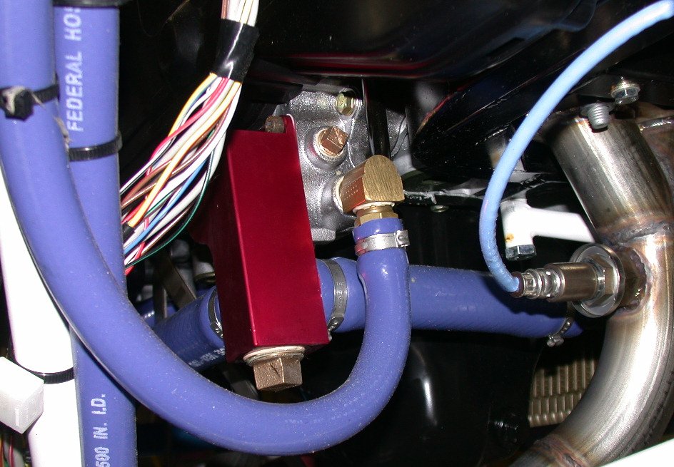
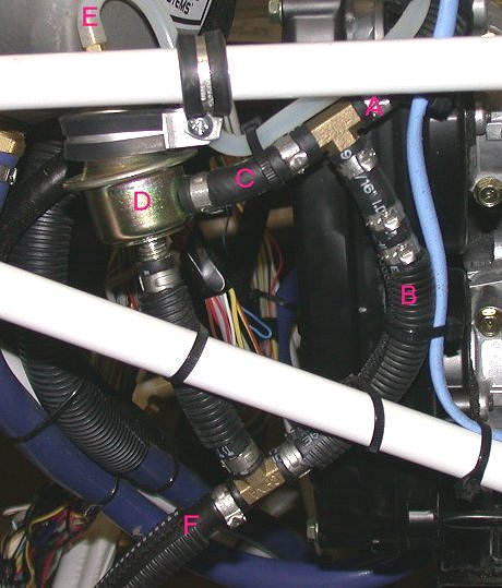
detailed pic of the water pump and related hoses. Click on pic for a
bigger one. This is from the aft looking forward. The one on the
far RT comes down from the RT tower, snakes around under the tubing for the
nose gear, then goes back up to the water pump LT side (on far LT of pic).
That's the one I am supposed to cut to tie in the heater.
Here's a side view of the water pump & hoses. Click on it for
big detail pic.
In removing my radiators for sending back to
Jan, I noticed that the little aluminum tubing vent bottle for the PSRU vent
was mounted poorly. The aluminum bar that was welded to it, to provide the
mounting surface, was welded on about 20 degrees from what it should be.
So, the top of the bottle is jammed against the top of the engine mount
plate, and the mount bar is about 20 degrees away from being flush to the
engine mount plate.
The screws attaching the PSRU vent bottle were probably barely long enough if the mount
bar was welded on right, so with the mount bar cocked way out from the
engine mount plate, the screws are not even long enough to reach the
(plastic!) locking portion of the nuts, much less go through them and have a
couple threads sticking out. No washers, either. Great quality & attention to detail.
June 9 - I read through parts of the
Eggenfellner Installation Manual. The problem is that many things have
changed since Gary wrote the manual, so in general, it's OK, but specifics
and pictures are outdated. My engine is not the same as Gary's. I
also found out recently my engine was supposed to come with an engine & prop
installation video, but I didn't get one. I asked Jan about it,
and he said his was kind of outdated, and that he is working on a new one.
Also, Tom Moore is working on a new installation video. I think his
engine is an H6, though, so it'll still be different from mine on engine
pics & details. Update web site from NHIS
1.0 hr + 5.0 hr doc
June 15 - This is Laconia Bike Week, one of the Big
Three events in motorcycling (the others are Sturgis and Daytona).
I've been here at NHIS for a week, and I'll be here until after the National
race on Sunday. We raced last weekend, and we race again this
weekend. The weather here in NH sucks so bad you can't believe it.
All spring, it's been so cold, I have to wear a down vest all day, every
day. Then, all last week and weekend, it was mid-90s and about 110% humidity.
Yesterday, the temps dropped about 40 degrees in one day, and it's been 50
degrees and intermittent rain ever since. The mosquitoes weren't
around much before last week, because it had been so cold, but now they're
here with a vengeance. I've also been busy with lots of phone calls
and meetings regarding building my hangar.
June 19 - Back home now. Remove PSRU vent bottle
to return to Eggenfellner. When I first wrote him about the bad
fit, he said I should sand the top of the tube a bit so it would fit.
I then sent him the above pics & explained that, for it to fit, about 1/2"
would have to be cut off the top. He said he'd swap it out. Then
I spent some time pondering my next move, and trying to figure out where to
put the cowl hinges. I got out the lower cowl and measured that I
should need about 11" of hinges on each side.
1.5 hr
June 20 - lay out shims for
lower cowl hinges. Cut, drill, cleco shims. Cut, drill,
cleco hinges. 1.0 hr + 1.0 hr doc
June 22 - catching up on this
6/30 - lots of updates to do. I found out my hangar plans have
been put on hold indefinitely while the local dildocrats now decide how
to come up with a "hangar policy". Back to the plane.
Countersink lower cowl hinges, dimple lower cowl hinge shims, cleco
lower shims and hinges. Studied layout for side hinges.
Called Van's and talked to Ken about what shims to use for the side
hinges. The plans don't show any for the sides, but show them for
the bottom hinges. Since the cowl is the same thickness
sides and bottom, I thought they should have the same shimming.
Ken said the shims, both for sides and bottom, are APPROXIMATE, and will
vary from one cowl to another. He reiterated that I MUST rivet
these before bolting the engine in; otherwise, I won't be able to get at
some of them for riveting. When things are approximate or "make to
fit", I wish the plans would say so, rather than giving fixed values
that builders will assume are concrete. Remove, polish, recleco
lower hinges & shims. 1.5 hr
June 23 - Double dimple lower
hinges for a better fit, rivet lower hinges. Lay out lower side hinges
and shims. 1.75 hr
June 24 - Get some 0.024"
stainless steel scraps from local sheet metal shop. Make & fit 3
firewall patches. Fit RT side cowl hinge & shim. Rivet RT cowl
shim & hinge. Drill & cleco LT cowl hinge & shim.
3.5 hr
Here
are the RT side and lower cowl hinges. The bottom hinges have been
riveted in, and the RT side is ready for riveting.
June 25 - Spent all morning at
Lawrence, MA RV flyin and seminars. After that, I went with Carsten
Schanche to his house, where he is building a 7A with Eggenfellner
supercharged STi engine, just like mine. He is slightly ahead of me in
the process. He used Proseal under the hinges - I didn't. I hope
that isn't a problem. I didn't see in the plans where it said to
do that. He gave me a whole bag full of parts to make a firewall
ground bar kit. I took about 100 pictures of his engine. Thanks
Carsten! At Lawrence, I also met John Sannizzaro, who was my partner
at the EAA SportAir sheet metal workshop back in 2002. John is putting
together a
wiring seminar with Bob Nuckolls at Plymouth, MA Aug 13 & 14 that I'll
be attending. Resumed prepping LT hinge & shim.
1.0 hr
These
are the brass plates and brass hardware that Carsten Schanche (president of
Aviation Association of NH) was kind enough to
give to me when I visited his house and saw his project. His RV-7A has
the same supercharged STi engine as mine. One thing I wanted to see
was what he did with the U720A&B, U620B,C,D pieces, but he hadn't done any
of those yet, either. He just installed his engine without them
for now, so I guess I'll be doing that, too.
June 26 early AM - Rivet LT
cowl hinge & shim. Spent some time pondering the fuel lines and pumps
assembly. I'm still bothered by the fact that they say it's wrong to
use rubber hose instead of metal lines to the selector valve, yet everything
else from the selector valve forward is not only rubber hose, but most all
of it is 5/16" instead of 3/8". Also trying to figure out how the
pressure regulator can be adjusted, as Robert Paisley says it needs to be
adjusted to reduce a too-rich condition at full boost. I don't see any
way to adjust this regulator. I was also wondering which oil line is
pressure & which is return, in case I decide to add an Accu-sump.
There's a VDO switch that I assume is the low oil pressure switch. I
wrote to the Eggenfellner list with questions about all these things and
several other questions. 1.5 hr
This is the fuel pressure regulator. Aside from there being no
adjustment on this, I couldn't understand how it could possibly work, with
bypass B there. The fuel comes in from A and goes out F. D is
the regulator. Eventually, I noticed the 2 extra clamps above the "B",
and realized they must have a check valve in there. I pulled this to
return to Jan for the proper one. Robert Paisley's testing has shown
that the ECM can't handle the fuel mixture right at full boost, so they
control it by adjusting the pressure down. I thought it was a rather
hokey band-aid fix to mask the real problem of the ECM, but Robert says it's
OK. E is the manifold pressure-compensating line.
June 26 PM - Paint nose gear
leg, go get bearing grease and grease nose wheel bearings. Clean out
WD630 and install zerk fitting. Insert U623-1 axle adapters, prep &
prime U813Cs, ream hole for WD631. I broke the adjuster nut on my good
US-made adjustable reamer, so I screwed around quite awhile trying to get
the last few thousands clearance in the hole in the WD631 steering stop.
I have a set of cheap adjustable reamers made in India, but they are pure
crap and 100% useless. Finally got the hole open enough to get the
bolt through it. Installed the WD632 bolt and torqued it. Made
up an order to MSC for more reamers. Spent a bunch of time trying to
find the U611 disk springs, and finally found them buried on the bench.
I cleaned and primed the U611 disk springs. Assembled nose gear wheel
and U813Cs onto the nose gear weldment (I forget the part number now).
I installed the nose gear leg attachment bolt to the engine frame. It
was a quite tight fit, but I used the rivet gun with a brass tip to slowly
drive it home. Then, I prepped the firewall patches and dimpled and
countersunk the rivet holes to attach the patches.
8.25 hr
Here's the nose gear leg, after priming and painting. When you order
an undrilled nose gear leg from Van's, apparently they ship them unpainted.
Here I am packing the wheel bearings. I suppose this would be a great
mystery to those who haven't done it before, but it's pretty simple.
Take a fistful of grease in your palm and scrape the edge of the bearing
across it repeatedly, until grease comes out the other end (of the bearing,
not of your hand). DO NOT just rub grease on it. You have to
force the grease all the way fully through all parts of the bearing. I
know they make bearing packing tools, but I've never used or even seen one
in person. This works, albeit a bit messy. I am using red
automotive wheel bearing grease from the local auto parts store. The
manual said to use some Shell Aircraft bearing grease, but I don't have any,
don't know where to get any, and am quite sure that anything designed to
work in a car's terrible environment, driving in salt, snow, rain for
200,000 miles should work just fine here. A tapered roller bearing is
a tapered roller bearing. Never mix greases from different sources,
though.
Here, the bearings are inserted into the wheels. The manual stressed
that you must grease the seal lip before putting the bearing/seal into
place. I had plenty of grease all over everything. I always like
to wipe an extra thick layer of grease around the outside of the bearing,
after packing it.
Here's the nose gear assembled, with the U813Cs. I think I will take
the U813Cs off for now - they are thin metal, and they look like they're
just begging to catch on something and get mangled.
Driving that nose gear leg bolt home with the 6x gun and an brass-tipped
rivet set. Even with the 6x gun, it went in slowly, but steadily.
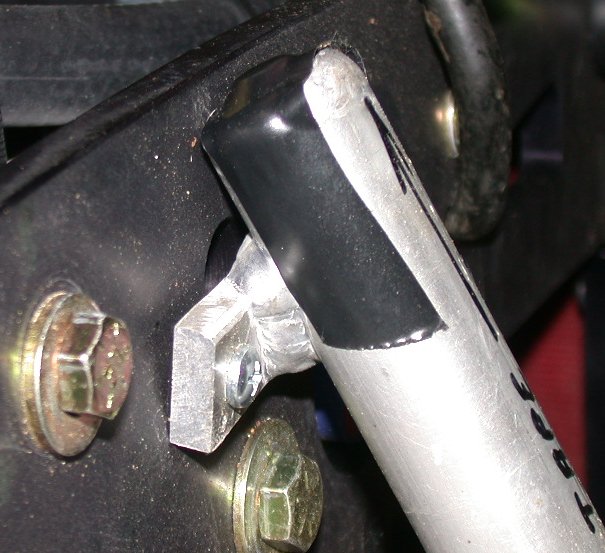
The nose gear is now mounted!! On the top of the nose gear leg, you
can see the shim stock sticking out, after I had tapered & curved the end of
it and forced it up between the gear leg and the engine frame, for an even
tighter fit. The pile of shim stock is on the engine stand leg.
I used a piece of 0.005", then cut it off and clamped it in place.
And here is the finished nose gear leg. The 0.005" shim stock is
shoved in there at least an inch. This removes all the play that was
necessary to get the leg to go up in there. I had to bend a lengthwise
curve into it and polish the end to a taper to get it to go in.
June 27 - prep firewall patches
for riveting and sealing. Process some pictures for web site.
1.0 hr + 1.25 hr doc
June 28 - mix Proseal and put on
firewall patches, with Karla's help and encouragement. We were going
to use solid rivets, but everything went to hell as soon as I mixed the
Proseal. I started getting it all over everything more & more, and
then one of the patches no longer lined up with the holes at all (after it
was covered in Proseal), so I had to rework that, getting more Proseal all
over everything in the process. By then I'd decided to give up on
using solid rivets and getting Proseal all over the gun & set, too, so I
just pop-riveted the patches into place. One problem with the Proseal
was that I had a 3.5 oz tube of it, and only needed to use about 1% of what
got mixed up. Exchanged numerous more emails with Jan and the
Eggenfellner list. Jan now says that I'll be getting my supercharger
and intercooler in OCTOBER!! I wrote back & said you gotta be
kidding me - you told me a few weeks ago that I'd have them in mid-June!
He had some tap-dancing answer, but that was not a fun surprise. There
was still no mention of all the other parts he still owes me, nor any word
on all the parts I have to keep sending him back for rework. After an
additional flurry of emails & questions, it seems that the pressure
regulator I have is not the one I need for a supercharged STi engine to run.
Jan says to send back the regulator & attached hoses, and he will swap them
for the correct adjustable regulator. I also noted in the Van's
catalog that they now carry a 1 oz container of Proseal, plus it looks like
it is not designed to use it all at once, as the 3.5 oz one was. For
my MSC order for reamers, I was also looking ahead to whatever I might need
for the wing bolts. I called Van's about wing and engine mount
bolts and reamers. For the wing bolts, even the hardware store bolts
look like a tight fit, and they measure 0.432 to 0.435, while the NAS bolts
are 0.436. Plus, the holes in the main gear leg frames are not quite
big enough, and/or slightly misaligned, so I thought I'd need to ream.
Van's said NO REAMING. Looks like I'll have to try to enlarge those
frame holes from the fwd side, rather than reaming it all out through the
wing root holes. Anyway, I also asked them how tight a fit the engine
mount bolts need to be. I'd planned to drill to U, using a special
long "U" drill I'd ordered from MSC, then reaming to 0.373. Van's said
no need to be that snug, but I'll probably do it that way, anyway, as I
already ordered the tools to do it with. It takes long bits, or an
extension, to drill the holes and clear the engine frame arms.
2.5 hr
June 29 - remove fuel pressure
regulator to send back to Jan for swapping for correct one. Work on
plan for drilling engine bolts, lining up the long bits, reamers, and
extensions I'll need, so I can drill them and clear the engine frame arms.
I also now see that I have to loosen the exhaust pipes so the drills will
clear them as I drill the 2 lower center holes. Sent email to
Eggenfellner list, asking what torque to use to put the exhaust pipes back
up. Spent some more time looking at the wing bolt fit. On the
top holes, the polished hardware store bolt slips all the way through to the
gear frame, then stops. On the lower holes, the bolt goes through the
first half of the center spar, but not the second half. That should be
quite interesting when I get to it. I mounted the nose wheel, then
used a selection of shim stock to jam in between the top of the nose gear
leg and the engine frame, for the tightest possible fit. I found a
0.005" shim, with the leading edge polished to an edge and the whole thing
bent to a lengthwise curve, could be shoved up in there about an inch, then
locked in place with a hose clamp. Removed the ECM and cut off excess
tie wraps holding things together temporarily. Loosened the headers
and tipped them out of the way. Although the Eggie list said 300 INCH
pounds of torque on the header nuts (later found the manual says 270 INCH
pounds), those nuts were on there TIGHT - I'd guess about 100 FOOT pounds.
Anyway, I got the headers loosened a bit & tipped out of the way. The center
brace must have been under a lot of strain, because the stainless steel
bracket totally ate the threads of the 6mm x 30mm bolt holding the braces to
the engine. So, I'll have to order another one of those. Then I
noticed that the heater hose had a little chafed spot, worn through to the
threads, in it. So, I pulled that off, and now I'll have to get more
heater hose. I don't know how it could have gotten chafed like that,
as nothing was near it, but it sure was chafed, so I pulled it. Jan is
using blue Federal Heater Hose 5526-050 1/2" ID. I'll try to find some
locally. It seems I'm taking bad crap off this engine much more than
I'm putting anything on it. Got engine and fuselage into final
position for drilling & reaming the engine mount bolt holes as soon as my MSC order arrives tomorrow. 6.75
hr
The arrow points to where the heater hose got chafed by something, sometime,
somehow. I don't know if was in installation, or shipping, or what.
There was nothing mounted near it. Anyway, I pulled this end of the
heater hose off, and will be replacing this end of it (the heater hose comes
as one piece and gets cut in the middle so each of the 2 cut ends go onto
the heater).
This is the tumble generator, from the wiring harness. The sticker
says "mount to frame", but this thing looks like a bitch to mount anywhere,
due to no surface to use for mounting. I asked the Eggie list, and
Robert Paisley said he just tie-wrapped his to some part of the frame.
This
prompted another question to the Eggie list - this fitting looks like it got
forgotten, but one of the other guys said it's been plugged inside.
Here it is!! All ready to mount, as soon as my MSC drill & reamer
order arrives tomorrow. The blue thing hanging down is the heater hose,
where
I had to remove one end from the engine, due to chafing damage in either
manufacturing, installation, or shipping.
June 30 - Called an A&P mechanic
friend of mine to ask about those Oetiker clamps Jan insists on using.
They are a huge pain to remove, and I'm sure they'll be a big pain to
install. Access looks difficult with them. You have to have
unobstructed right-angle clearance to get the tool onto them. I've never liked them or believed that there's anything wrong
with aircraft quality worm clamps, like the Aero Seal that ACS sells.
Jim says he never heard of Oetiker clamps, and he uses Aero Seal worm clamps
all the time on certificated aircraft. That about clinches it for me.
While it would be foolish to replace existing clamps, I will use Aero Seal
hose clamps when I replace all the many things I've had to remove from this
engine. I am also reworking the fuel pumps setup I got from Jan,
mainly to get rid of all the 5/16" hose he is using, and replace it with
3/8". Worked on updating the last week's worth of work on the web
site. Started drilling the engine holes with the 12" "U" drill
bit I got from MSC. There was a lot of chatter, so I pulled the engine
away from the firewall and
enlarged the hole to 5/16" with a Unibit. Then I put the engine back
in place and drilled it with the "U" bit, then used a 0.3730 reamer on an
extension to take it up to final size. The bolt slid in nicely.
I repeated for the other top corner. I made the mistake of doing this
process for the bottom corner holes, too. While there was plenty of
left-right flex for the top 2 holes, there was none on the bottom corner
holes (it's essentially a solid tube from side to side), I ended up
with the 5/16" holes a bit to the outside of where the frame holes were
(maybe 1/16"). After drilling to U size and reaming to 0.3730, the
holes were a bit elongated to the outside, but there wasn't anything I could
do about it. In hindsight, I should have just used the "U" drill
directly on the 2 lower corner holes. With the frame bolted in place
at the top, the frame rigidity would probably have kept the bit from
chattering in the hole. And I probably should have done those 2 bottom
outside holes first, as there is no flexibility in the frame for where they
are located. Oh well. Then, I tightened up the corner
bolts, and took some of the weight off the hoist, and "U" drilled and reamed
the 2 bottom center bolts. They were a perfect slip fit, so very snug
there. Again, in hindsight, I should have taken a bit more weight off
the hoist, to let the frame sag down a bit more (oddly, the center moved
DOWN as I took weight off the hoist and onto the nose gear leg - I'd have
figured it'd move up), but there's no way to really tell where the hole is
going to end up on the plate until you drill it. The hole ended up being a bit
too close to the rivet head of one of the rivets holding the engine mount
reinforcement plate on the inside of the firewall. The bolt head on
the RT lower center just barely cleared the shop head of one of those
rivets. If I'd let the frame come down a bit more (by taking more
weight off the hoist), it would have cleared the rivet head by a bit more.
Oh well again. Not a biggie; the bolt head did clear the rivet shop
head. With the engine fully mounted, I took the hoist away and started
cleaning up the shop some; big mess. Oh, and the engine mount bolts
from Van's are AN6-24. With the Eggenfellner frame, each corner bolt
needed 4 washers and the 2 bottom center bolts needed 3 washers. So,
if you're ordering bolts, probably some -22 would be ideal, but you might
want to get some -21 and -23, too. The -24s work fine with washers,
though. Now that the engine is mounted, I can see 2 problems.
First, it's harder to get access to mount other things to the engine and
firewall, but it's a chicken-and-egg thing, because I needed the engine in
place to determine where to put these things. Second, while I still am
shocked that Jan said it'd be OCTOBER before I get my supercharger and
intercooler setup, I still don't dare mount things to the firewall, like
the coolant tank, ground plate, and ECM harness hole, because I need to have
the supercharger and intercooler mounted first, to make sure I don't install
something in the way of those fixed items. I emailed Robert Paisley
about it, hoping to get some dimensions he used or recommends. He
suggested I look over his plane at Oshkosh & take my own measurements from
it.
3.5 hr + 4.0 hr doc
Here's the 12" U-letter drill I ordered from MSC, for drilling the engine
mount holes in the firewall.
Here's the 0.3730" reamer and 18" extension I got from MSC for this job.
Here it is, standing on 3 legs!
Well, I managed to get it bolted on in June! I
finished the job about 11 PM on June 30.
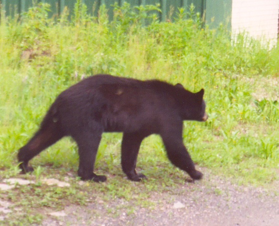
A bear
has been coming around the house several times lately, going after the seeds
in the birdfeeder. We took the seed inside, but he came back a few
more times to see if there was any more food available. I saw him once
before, but I didn't have my camera with me. This time, I used Karla's
film camera to get some shots, then scanned them. He had wrecked the
feeders on a previous visit, so I'd fixed them and put the seed away.
One was on a 3/4" steel water pipe driven several feet in the ground.
Even though he seems to be a pretty small, young bear, he folded the pipe
over like it was nothing. At one point this day, he stood up next to
that feeder again and I rapped on the window to get him to move away from
it. Click on any to see a bigger pic. I saw a big bobcat walk
across the yard last year, but he was gone by the time I got the camera out.
 This
was taken right after I had rolled the engine and pallet up so the pallet is
standing on its edge and the engine is in its proper position. As I
gradually lifted the load and the pallet started tipping up, I kept
loosening the front tiedowns and tightening the front ones, until they were
even. I didn't take a pic of it, but I started with the pallet flat on
the ground and the front tiedowns (RT in this pic) much shorter than the
rear ones. If I'd started with them all the same length, the pallet
would have flipped to this position immediately (and quickly), possibly
striking the exhaust pipes or front of the engine on the ground & damaging
them.
This
was taken right after I had rolled the engine and pallet up so the pallet is
standing on its edge and the engine is in its proper position. As I
gradually lifted the load and the pallet started tipping up, I kept
loosening the front tiedowns and tightening the front ones, until they were
even. I didn't take a pic of it, but I started with the pallet flat on
the ground and the front tiedowns (RT in this pic) much shorter than the
rear ones. If I'd started with them all the same length, the pallet
would have flipped to this position immediately (and quickly), possibly
striking the exhaust pipes or front of the engine on the ground & damaging
them.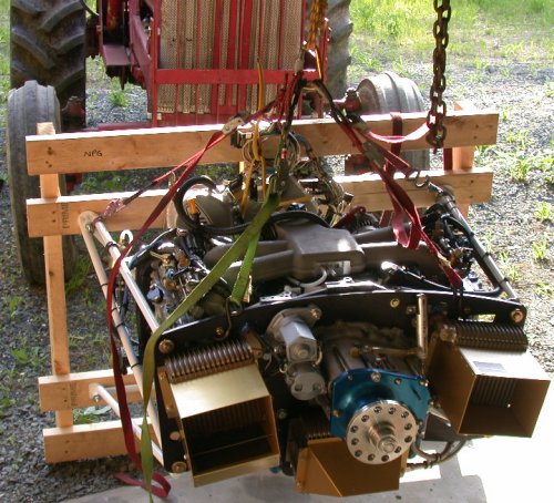 Here's
a front pic of the engine, after I'd gotten it flipped over to horizontal.
The 4 motorcycle tiedowns go to an oval carabiner, which is connected with 2
rock climbing slings to 2 more 'biners, and then one 'biner is connected to
the chain on the tractor bucket. The other sling & 'biner is for
connecting to the crane.
Here's
a front pic of the engine, after I'd gotten it flipped over to horizontal.
The 4 motorcycle tiedowns go to an oval carabiner, which is connected with 2
rock climbing slings to 2 more 'biners, and then one 'biner is connected to
the chain on the tractor bucket. The other sling & 'biner is for
connecting to the crane.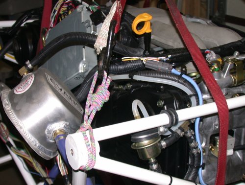 These next 4 pics show the details of how I slung the engine. It
worked out very well. This is the upper RT mount. The 1/4" rock
climbing sling is thin enough that it can wrap around the mount point
without interfering with either the mount face or mount bolt. DON'T
try this with 1/4" hardware store rope! The motorcycle tiedown hooks
to the sling and to the central oval carabiner. I highly recommend the
use of motorcycle tiedowns for this, because it's so easy to control the tip
and tilt of the engine by carefully adjusting the lengths of the tiedowns.
Don't use crappy Chinese tiedowns for this! Use US-made Ancra tiedowns
rated for at least 2000 pounds each.
These next 4 pics show the details of how I slung the engine. It
worked out very well. This is the upper RT mount. The 1/4" rock
climbing sling is thin enough that it can wrap around the mount point
without interfering with either the mount face or mount bolt. DON'T
try this with 1/4" hardware store rope! The motorcycle tiedown hooks
to the sling and to the central oval carabiner. I highly recommend the
use of motorcycle tiedowns for this, because it's so easy to control the tip
and tilt of the engine by carefully adjusting the lengths of the tiedowns.
Don't use crappy Chinese tiedowns for this! Use US-made Ancra tiedowns
rated for at least 2000 pounds each.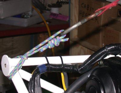 This is the sling holding the upper LT mount
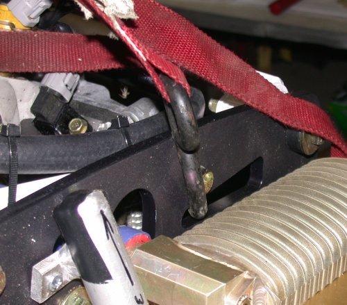 The 2 tiedowns at the front of the engine hook directly into convenient
slots in the aluminum fwd frame plate. The bolt attaching the plate to
the tubing frame keeps the tiedown hook from moving around. In the
foreground, note the poorly made/attached aluminum vent bottle for the PSRU.
More details on that later.
The 2 tiedowns at the front of the engine hook directly into convenient
slots in the aluminum fwd frame plate. The bolt attaching the plate to
the tubing frame keeps the tiedown hook from moving around. In the
foreground, note the poorly made/attached aluminum vent bottle for the PSRU.
More details on that later.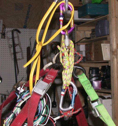 This shows where all the tiedowns come together, and where I had removed the
red sling to get the engine up higher in the crane. The 4 tiedowns
hook into the oval carabiner, and the purple 'biner connects that directly
to the chain hook on the crane. By having 2 sets of 'biner & sling
above the gold oval 'biner, I can easily switch the load from crane to
tractor and back. The yellow Romex is just there to loosely hold the wiring
harness up out of the way.
This shows where all the tiedowns come together, and where I had removed the
red sling to get the engine up higher in the crane. The 4 tiedowns
hook into the oval carabiner, and the purple 'biner connects that directly
to the chain hook on the crane. By having 2 sets of 'biner & sling
above the gold oval 'biner, I can easily switch the load from crane to
tractor and back. The yellow Romex is just there to loosely hold the wiring
harness up out of the way. Here are the engine and frame, facing each other, ready to be joined in holy
matrimony forever.
Here are the engine and frame, facing each other, ready to be joined in holy
matrimony forever.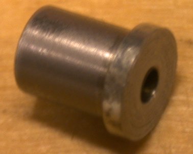 The collar on the Eggenfellner frame comes pre-drilled to about 1/4".
I wanted to make sure my pilot hole into the gear leg was perfectly
centered in the hole in the frame collar, so I made this drill bushing. The body OD is matched
to the hole in the collar, as it comes from Eggenfeller. The hole in
the bushing is
1/8". The lip gives me something to grasp and with which to remove the
bushing. Without the bushing, it's hard to make sure your gear leg
pilot hole is perfectly centered in the pilot hole in the frame. If
the leg hole isn't centered perfectly, the
leg will be rotated a bit when you start reaming both the frame hole and the
leg hole together, and the leg will no longer be perfectly vertical.
The collar on the Eggenfellner frame comes pre-drilled to about 1/4".
I wanted to make sure my pilot hole into the gear leg was perfectly
centered in the hole in the frame collar, so I made this drill bushing. The body OD is matched
to the hole in the collar, as it comes from Eggenfeller. The hole in
the bushing is
1/8". The lip gives me something to grasp and with which to remove the
bushing. Without the bushing, it's hard to make sure your gear leg
pilot hole is perfectly centered in the pilot hole in the frame. If
the leg hole isn't centered perfectly, the
leg will be rotated a bit when you start reaming both the frame hole and the
leg hole together, and the leg will no longer be perfectly vertical.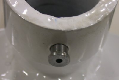 Here is the bushing in place on the collar, but not yet pushed all the way
in.
Here is the bushing in place on the collar, but not yet pushed all the way
in.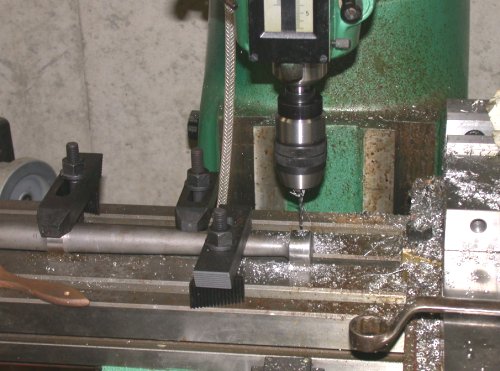 Here is the nose gear leg, mounted to the mill for drilling. I made
sure the drill bit would be passing from the pilot hole I started, directly
through the center of the gear leg.
Here is the nose gear leg, mounted to the mill for drilling. I made
sure the drill bit would be passing from the pilot hole I started, directly
through the center of the gear leg.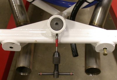 After drilling the leg and collar out to "M" drill size, I assembled the leg
into the frame, and began using my adjustable reamer to take the hole out a
few thousandths with each pass, until I could just start the bolt threads
into each hole. The threads are a few thousandths smaller than the
bolt body, so when I can just barely slip the bolt in from each end, up to
the bolt shank, I know it's ready to be pounded the rest of the way in.
The red tape tells me where the adjuster nut ended up when I did the bolt
for the main gear, so I'll know when I am getting close.
After drilling the leg and collar out to "M" drill size, I assembled the leg
into the frame, and began using my adjustable reamer to take the hole out a
few thousandths with each pass, until I could just start the bolt threads
into each hole. The threads are a few thousandths smaller than the
bolt body, so when I can just barely slip the bolt in from each end, up to
the bolt shank, I know it's ready to be pounded the rest of the way in.
The red tape tells me where the adjuster nut ended up when I did the bolt
for the main gear, so I'll know when I am getting close.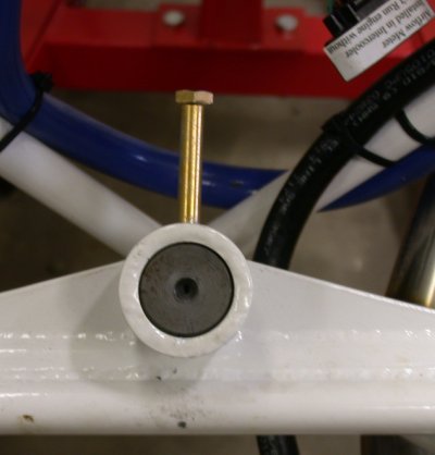 Here's the bolt, pushed in as far as I can by hand. I made sure it's
the same fit in the hole from the other end, too. Now, I'm just waiting for the
proper length bolt from ACS, and I'll drive it home. In the upper RT
corner, note one of the little instruction tags Jan puts on various parts of
the engine. They are helpful. NOTE - I finished the
job
Here's the bolt, pushed in as far as I can by hand. I made sure it's
the same fit in the hole from the other end, too. Now, I'm just waiting for the
proper length bolt from ACS, and I'll drive it home. In the upper RT
corner, note one of the little instruction tags Jan puts on various parts of
the engine. They are helpful. NOTE - I finished the
job 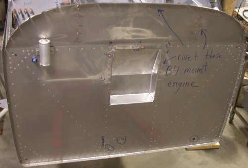 This firewall detail shows where I had to get the F745s and F643-1 riveted
on before mounting the engine. It also shows the 2 nutplates in the
lower center that had to be removed, and the large 3/4" hole in the lower LT
(RT in the pic) where the original plans called for placing the fuel line
bulkhead fitting. The fitting and the nutplates had to come out
because they interfere with the lower engine frame. The nutplate holes
& bad fuel line hole all need to be patched over with stainless steel. You can see the 4
engine mount holes that came pre-drilled to 1/4" as part of the QB kit.
The red dots inside the top 2 engine mount holes are where the engine frame
was lining up. Fortunately, I was able to figure out that the hoist
rig I had was pulling the frame inward. Once I released that inward
pull, the frame is actually now outside the firewall holes. So, it
will be easy to pull it in to match, just by tightening the crane hoist tiedowns. I thought I might have to remove the brake fluid reservoir,
but, for now, it's OK where it is.
This firewall detail shows where I had to get the F745s and F643-1 riveted
on before mounting the engine. It also shows the 2 nutplates in the
lower center that had to be removed, and the large 3/4" hole in the lower LT
(RT in the pic) where the original plans called for placing the fuel line
bulkhead fitting. The fitting and the nutplates had to come out
because they interfere with the lower engine frame. The nutplate holes
& bad fuel line hole all need to be patched over with stainless steel. You can see the 4
engine mount holes that came pre-drilled to 1/4" as part of the QB kit.
The red dots inside the top 2 engine mount holes are where the engine frame
was lining up. Fortunately, I was able to figure out that the hoist
rig I had was pulling the frame inward. Once I released that inward
pull, the frame is actually now outside the firewall holes. So, it
will be easy to pull it in to match, just by tightening the crane hoist tiedowns. I thought I might have to remove the brake fluid reservoir,
but, for now, it's OK where it is.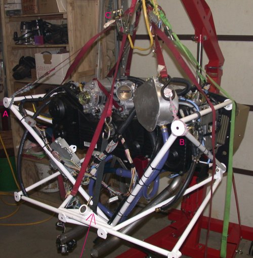 Here's the new hoist method. I put a sling on the frame where the nose
gear mates, at the red arrow, then hooked a ratchet tiedown (C) from that to
the carabiner on top. Once I tightened up the ratchet tiedown to
relieve the inward pressure on the upper corners (at A and B), the frame
relaxed and will fit the firewall just fine.
Here's the new hoist method. I put a sling on the frame where the nose
gear mates, at the red arrow, then hooked a ratchet tiedown (C) from that to
the carabiner on top. Once I tightened up the ratchet tiedown to
relieve the inward pressure on the upper corners (at A and B), the frame
relaxed and will fit the firewall just fine.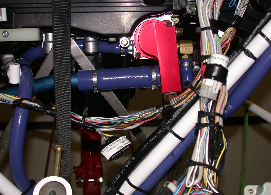
 In removing my radiators for sending back to
Jan, I noticed that the little aluminum tubing vent bottle for the PSRU vent
was mounted poorly. The aluminum bar that was welded to it, to provide the
mounting surface, was welded on about 20 degrees from what it should be.
So, the top of the bottle is jammed against the top of the engine mount
plate, and the mount bar is about 20 degrees away from being flush to the
engine mount plate.
In removing my radiators for sending back to
Jan, I noticed that the little aluminum tubing vent bottle for the PSRU vent
was mounted poorly. The aluminum bar that was welded to it, to provide the
mounting surface, was welded on about 20 degrees from what it should be.
So, the top of the bottle is jammed against the top of the engine mount
plate, and the mount bar is about 20 degrees away from being flush to the
engine mount plate. 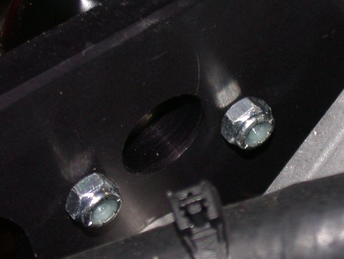 The screws attaching the PSRU vent bottle were probably barely long enough if the mount
bar was welded on right, so with the mount bar cocked way out from the
engine mount plate, the screws are not even long enough to reach the
(plastic!) locking portion of the nuts, much less go through them and have a
couple threads sticking out. No washers, either. Great quality & attention to detail.
The screws attaching the PSRU vent bottle were probably barely long enough if the mount
bar was welded on right, so with the mount bar cocked way out from the
engine mount plate, the screws are not even long enough to reach the
(plastic!) locking portion of the nuts, much less go through them and have a
couple threads sticking out. No washers, either. Great quality & attention to detail.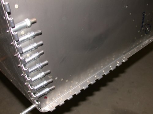 Here
are the RT side and lower cowl hinges. The bottom hinges have been
riveted in, and the RT side is ready for riveting.
Here
are the RT side and lower cowl hinges. The bottom hinges have been
riveted in, and the RT side is ready for riveting.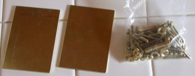 These
are the brass plates and brass hardware that Carsten Schanche (president of
These
are the brass plates and brass hardware that Carsten Schanche (president of
 This is the fuel pressure regulator. Aside from there being no
adjustment on this, I couldn't understand how it could possibly work, with
bypass B there. The fuel comes in from A and goes out F. D is
the regulator. Eventually, I noticed the 2 extra clamps above the "B",
and realized they must have a check valve in there. I pulled this to
return to Jan for the proper one. Robert Paisley's testing has shown
that the ECM can't handle the fuel mixture right at full boost, so they
control it by adjusting the pressure down. I thought it was a rather
hokey band-aid fix to mask the real problem of the ECM, but Robert says it's
OK. E is the manifold pressure-compensating line.
This is the fuel pressure regulator. Aside from there being no
adjustment on this, I couldn't understand how it could possibly work, with
bypass B there. The fuel comes in from A and goes out F. D is
the regulator. Eventually, I noticed the 2 extra clamps above the "B",
and realized they must have a check valve in there. I pulled this to
return to Jan for the proper one. Robert Paisley's testing has shown
that the ECM can't handle the fuel mixture right at full boost, so they
control it by adjusting the pressure down. I thought it was a rather
hokey band-aid fix to mask the real problem of the ECM, but Robert says it's
OK. E is the manifold pressure-compensating line.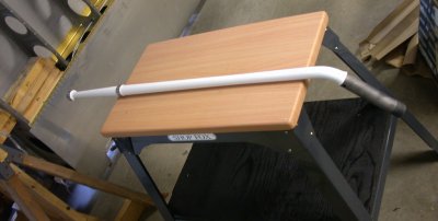 Here's the nose gear leg, after priming and painting. When you order
an undrilled nose gear leg from Van's, apparently they ship them unpainted.
Here's the nose gear leg, after priming and painting. When you order
an undrilled nose gear leg from Van's, apparently they ship them unpainted.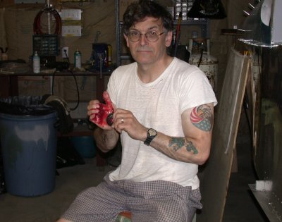 Here I am packing the wheel bearings. I suppose this would be a great
mystery to those who haven't done it before, but it's pretty simple.
Take a fistful of grease in your palm and scrape the edge of the bearing
across it repeatedly, until grease comes out the other end (of the bearing,
not of your hand). DO NOT just rub grease on it. You have to
force the grease all the way fully through all parts of the bearing. I
know they make bearing packing tools, but I've never used or even seen one
in person. This works, albeit a bit messy. I am using red
automotive wheel bearing grease from the local auto parts store. The
manual said to use some Shell Aircraft bearing grease, but I don't have any,
don't know where to get any, and am quite sure that anything designed to
work in a car's terrible environment, driving in salt, snow, rain for
200,000 miles should work just fine here. A tapered roller bearing is
a tapered roller bearing. Never mix greases from different sources,
though.
Here I am packing the wheel bearings. I suppose this would be a great
mystery to those who haven't done it before, but it's pretty simple.
Take a fistful of grease in your palm and scrape the edge of the bearing
across it repeatedly, until grease comes out the other end (of the bearing,
not of your hand). DO NOT just rub grease on it. You have to
force the grease all the way fully through all parts of the bearing. I
know they make bearing packing tools, but I've never used or even seen one
in person. This works, albeit a bit messy. I am using red
automotive wheel bearing grease from the local auto parts store. The
manual said to use some Shell Aircraft bearing grease, but I don't have any,
don't know where to get any, and am quite sure that anything designed to
work in a car's terrible environment, driving in salt, snow, rain for
200,000 miles should work just fine here. A tapered roller bearing is
a tapered roller bearing. Never mix greases from different sources,
though.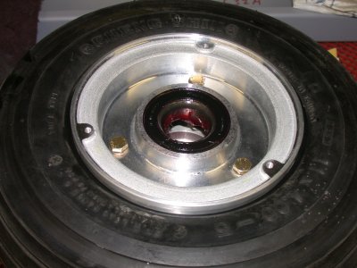 Here, the bearings are inserted into the wheels. The manual stressed
that you must grease the seal lip before putting the bearing/seal into
place. I had plenty of grease all over everything. I always like
to wipe an extra thick layer of grease around the outside of the bearing,
after packing it.
Here, the bearings are inserted into the wheels. The manual stressed
that you must grease the seal lip before putting the bearing/seal into
place. I had plenty of grease all over everything. I always like
to wipe an extra thick layer of grease around the outside of the bearing,
after packing it.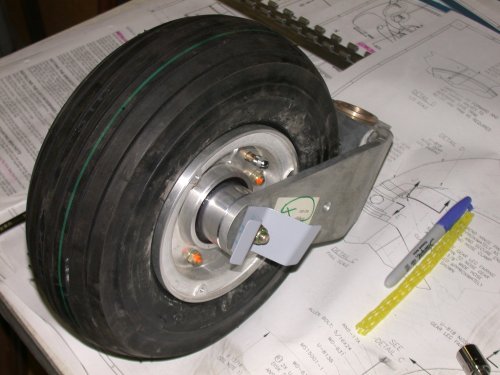 Here's the nose gear assembled, with the U813Cs. I think I will take
the U813Cs off for now - they are thin metal, and they look like they're
just begging to catch on something and get mangled.
Here's the nose gear assembled, with the U813Cs. I think I will take
the U813Cs off for now - they are thin metal, and they look like they're
just begging to catch on something and get mangled.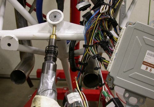 Driving that nose gear leg bolt home with the 6x gun and an brass-tipped
rivet set. Even with the 6x gun, it went in slowly, but steadily.
Driving that nose gear leg bolt home with the 6x gun and an brass-tipped
rivet set. Even with the 6x gun, it went in slowly, but steadily.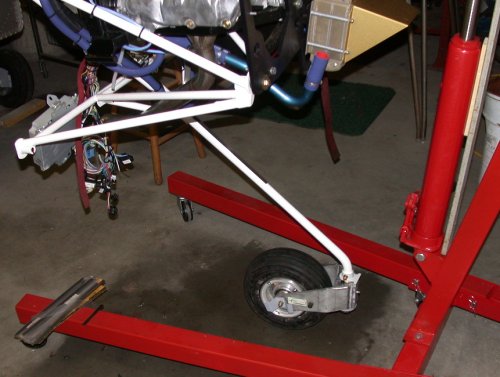 The nose gear is now mounted!! On the top of the nose gear leg, you
can see the shim stock sticking out, after I had tapered & curved the end of
it and forced it up between the gear leg and the engine frame, for an even
tighter fit. The pile of shim stock is on the engine stand leg.
I used a piece of 0.005", then cut it off and clamped it in place.
The nose gear is now mounted!! On the top of the nose gear leg, you
can see the shim stock sticking out, after I had tapered & curved the end of
it and forced it up between the gear leg and the engine frame, for an even
tighter fit. The pile of shim stock is on the engine stand leg.
I used a piece of 0.005", then cut it off and clamped it in place.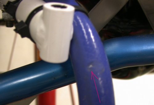 The arrow points to where the heater hose got chafed by something, sometime,
somehow. I don't know if was in installation, or shipping, or what.
There was nothing mounted near it. Anyway, I pulled this end of the
heater hose off, and will be replacing this end of it (the heater hose comes
as one piece and gets cut in the middle so each of the 2 cut ends go onto
the heater).
The arrow points to where the heater hose got chafed by something, sometime,
somehow. I don't know if was in installation, or shipping, or what.
There was nothing mounted near it. Anyway, I pulled this end of the
heater hose off, and will be replacing this end of it (the heater hose comes
as one piece and gets cut in the middle so each of the 2 cut ends go onto
the heater).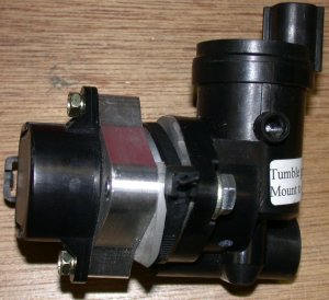 This is the tumble generator, from the wiring harness. The sticker
says "mount to frame", but this thing looks like a bitch to mount anywhere,
due to no surface to use for mounting. I asked the Eggie list, and
Robert Paisley said he just tie-wrapped his to some part of the frame.
This is the tumble generator, from the wiring harness. The sticker
says "mount to frame", but this thing looks like a bitch to mount anywhere,
due to no surface to use for mounting. I asked the Eggie list, and
Robert Paisley said he just tie-wrapped his to some part of the frame.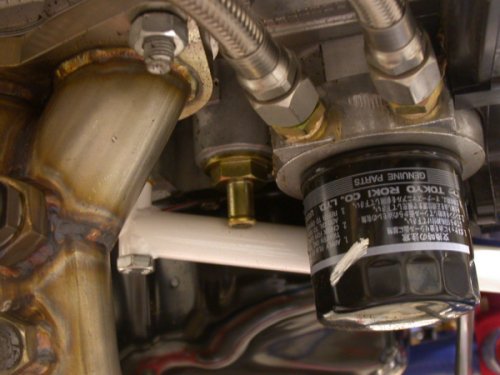 This
prompted another question to the Eggie list - this fitting looks like it got
forgotten, but one of the other guys said it's been plugged inside.
This
prompted another question to the Eggie list - this fitting looks like it got
forgotten, but one of the other guys said it's been plugged inside.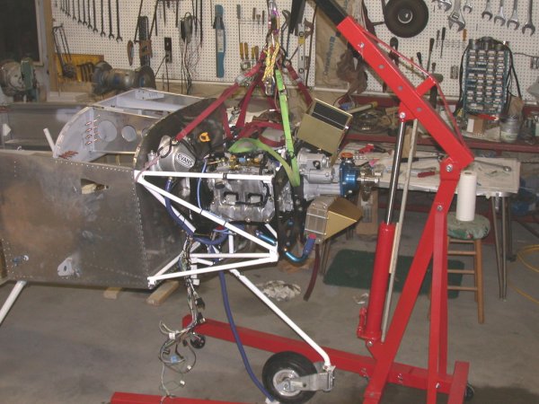 Here it is!! All ready to mount, as soon as my MSC drill & reamer
order arrives tomorrow. The blue thing hanging down is the heater hose,
where
I had to remove one end from the engine, due to chafing damage in either
manufacturing, installation, or shipping.
Here it is!! All ready to mount, as soon as my MSC drill & reamer
order arrives tomorrow. The blue thing hanging down is the heater hose,
where
I had to remove one end from the engine, due to chafing damage in either
manufacturing, installation, or shipping.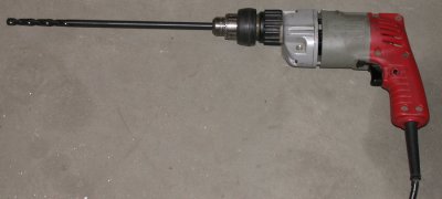 Here's the 12" U-letter drill I ordered from MSC, for drilling the engine
mount holes in the firewall.
Here's the 12" U-letter drill I ordered from MSC, for drilling the engine
mount holes in the firewall.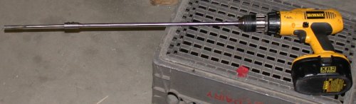 Here's the 0.3730" reamer and 18" extension I got from MSC for this job.
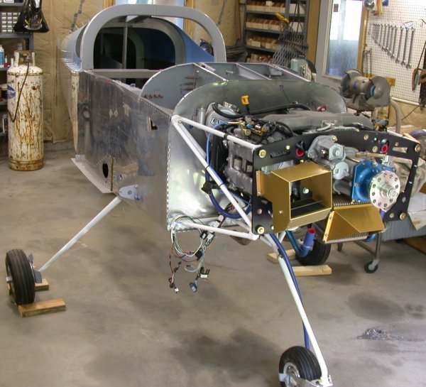 Here it is, standing on 3 legs!