 My missing ECM warning light wire had been labeled and tucked into the
harness to the engine, which was then tightly wrapped with silicone tape.
So I cut into the tape some, pulled the wire out, and retaped the harness.
My missing ECM warning light wire had been labeled and tucked into the
harness to the engine, which was then tightly wrapped with silicone tape.
So I cut into the tape some, pulled the wire out, and retaped the harness.MARCH, 2007 AVIONICS, ELECTRICS, & CONTROLS
If it's general supporting wiring, it's on this page. If it's strictly engine wiring, it's on the engine page, so be sure to check there for details.
March 1 - researching and documenting Grand Rapids Technologies EIS4000 setup values. For Eggenfellner engines, we are not using most of the EIS pages. My Starband ISP has had my ftp access to the web server down for the last 3 days, so I am unable to send updates to the server. I assume they will eventually fix the problem. But they are the only option when you live out in the boonies like I do. I will be putting my EIS config doc on the same page as my other electric/avionics documentation. Worked a couple hours in the evening on more EIS configuration setup and documentation. From reading the EIS manual more, I found out that the EIS isn't quite a cumbersome to program as I'd thought; if you HOLD DOWN a button, it will rapidly repeat. That's sure better than pressing a button 500 times! 2.0 hr
March 2 - Starband is still "working on" their broken FTP server, so no web site updates all week. Maybe next week. Last night, I figured out that the EIS "Tach P/R" value of 3 that I am using is probably wrong. I now think it should be 2, and will try that at the first opportunity.
March 4 - reconfigure EIS & set up more values. Install MT prop controller wiring (twice, because the first time I did it, I forgot to include the panel breaker in the circuit). Also spent some time planning the layout of the AoA computer and the GRT ARINC-429 module. 6.5 hr
March 5 - Starband FTP server is STILL down. I called yet again. I got a call back in the late afternoon, saying it was finally fixed.
March 7 - called GRT with some questions and to order an additional fuel pressure sensor; this one to use as a supercharger pressure sensor. No answer, left message.
March 9 - connected with Sandy at GRT and ordered the supercharger pressure sensor, as well as their GPS module. Sandy was quite helpful in helping me pick out the right sensor. Sandy also answered a couple other questions for me about the connectors on the back of the ARINC-429 module. GRT's customer service is SO good. They are also very good at facilitating upgrades. I wanted the IFR-certified version of their GPS, due out by the end of the year. Sandy said that, if I buy the GPS now, I get full credit on it toward the IFR GPS when it comes out. GRT customer service is VERY good about things like that. She's also sending me some wiring connectors and related accessories for my ARINC-429 module. Also talked to Eckhard and asked him to get my Garmin 330 and 340 on order, so I can start wiring them up.
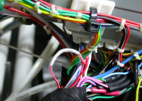
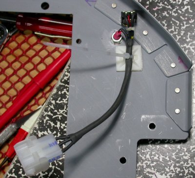
March 10 - After Carsten and Jan told me the wire color and pin number for the missing ECM warning light wire, I found it easily, labeled and locked into the part of the harness that had been tightly wrapped with silicone tape. No wonder I couldn't find it. Pulled that from the harness, in case things ever change enough that I can use it. Installed positive wire for second battery. Re-examined switch panel and considered making a new one; longer and taller, so I'll have more room for switch labels. Using the standard 12" long 1.5" x 1.5" pieces from ACS was convenient, but the size is marginal. Decided to stick with what I have for now. Cut hole in subpanel for GRT ARINC-429 module and installed that. Mounted AoA computer to top of BMA A/P controller, using double-sided tape. Started wiring panel DVM. 4.25 hr
My missing ECM warning light wire had been labeled and tucked into the
harness to the engine, which was then tightly wrapped with silicone tape.
So I cut into the tape some, pulled the wire out, and retaped the harness.
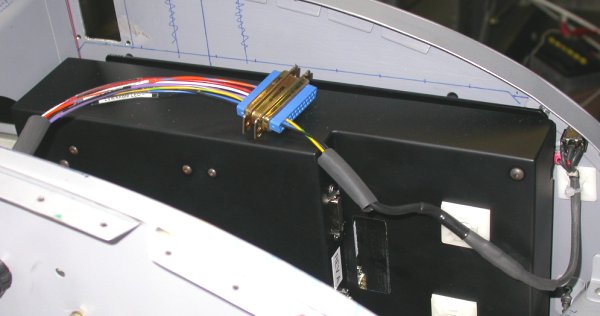
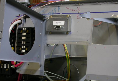 here is the Grand Rapids ARINC-429 module, installed into the subpanel.
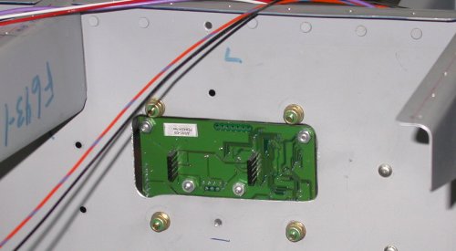 This
is the back of the ARINC-429 module (fwd side). GRT uses a very odd
connector arrangement here, so it has to be mounted to allow access to
connectors on both the face and the back of it. I'll have to call GRT,
to find out what sort of connector to use here. UPDATE - I
later found out this is not AT ALL how this gets
mounted. It plugs onto the motherboard at the back of the display.
This
is the back of the ARINC-429 module (fwd side). GRT uses a very odd
connector arrangement here, so it has to be mounted to allow access to
connectors on both the face and the back of it. I'll have to call GRT,
to find out what sort of connector to use here. UPDATE - I
later found out this is not AT ALL how this gets
mounted. It plugs onto the motherboard at the back of the display.
March 11 - continue wiring DVM. Plan and cut panel for DVM and DVM selector switch. Spent some time fooling with the fit between the DVM and the Blue Mountain EFIS display. After I finally got the DVM wiring complete, using a 3 pin Molex connector, I decided it'd be much better to use one DB-25 for all these panel indicator signal connections, rather than many Molex connectors. So, I cut off the Molex connector and redid the DVM wiring via a DB-25. Also wired up about 6 more circuits to the DB-25. That sure is a lot of time spent wiring up a DVM! 8.5 hr
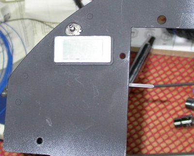 Here
are the DVM and its selector switch installed in the upper LT corner of the
panel, just clearing the back of the overlapping BMA display. I
painted this section flat black (final color), as I won't be able to remove
these easily without disturbing the soldered wiring. The ON-OFF-ON
SPDT switch lets me select either battery or select "OFF".
Here
are the DVM and its selector switch installed in the upper LT corner of the
panel, just clearing the back of the overlapping BMA display. I
painted this section flat black (final color), as I won't be able to remove
these easily without disturbing the soldered wiring. The ON-OFF-ON
SPDT switch lets me select either battery or select "OFF".
 To make
the panel removable without disturbing the DVM wires, I wired the DVM, with
22ga wires, to a Molex connector. The wires coming out of the DVM are
about 30 gage, so they're very delicate, and I spent a lot of time making
sure the wiring behind the panel was well secured and protected. A
critical part of my design is that the panel will always be easily
removable, and that it will come back at least a few inches without
disconnecting anything.
To make
the panel removable without disturbing the DVM wires, I wired the DVM, with
22ga wires, to a Molex connector. The wires coming out of the DVM are
about 30 gage, so they're very delicate, and I spent a lot of time making
sure the wiring behind the panel was well secured and protected. A
critical part of my design is that the panel will always be easily
removable, and that it will come back at least a few inches without
disconnecting anything.
 Then, I
realized that I didn't want to have to do these big old Molex connectors for
every panel component, so I redid the 3 DVM wires to a DB-25 connector.
I then wired in several more circuits that were waiting for the chance to
come to the panel. The black thing is the BMA EFIS display. It
wraps behind the panel for a couple inches LT of the cutout. So, the
DVM actually overlaps the back of the display, on the front of the panel,
and the display is just barely clearing the DVM mount bolt and the switch.
The whole panel is laid out this tight, to conserve space and make it all
fit. Above the BMA display, you can see the hole for the AoA indicator
and to the RT of that (in the pic) is the triangular area reserved for my
indicators. See here for the
drawing of this indicators area, mentioned earlier in
January and
February.
Then, I
realized that I didn't want to have to do these big old Molex connectors for
every panel component, so I redid the 3 DVM wires to a DB-25 connector.
I then wired in several more circuits that were waiting for the chance to
come to the panel. The black thing is the BMA EFIS display. It
wraps behind the panel for a couple inches LT of the cutout. So, the
DVM actually overlaps the back of the display, on the front of the panel,
and the display is just barely clearing the DVM mount bolt and the switch.
The whole panel is laid out this tight, to conserve space and make it all
fit. Above the BMA display, you can see the hole for the AoA indicator
and to the RT of that (in the pic) is the triangular area reserved for my
indicators. See here for the
drawing of this indicators area, mentioned earlier in
January and
February.
March 12 - Cleanup from recent work. Remove increasingly-difficult-to-remove removable electrics panel, to get better access to the grounds plate. Install ground wires for DVM and MT prop controller. Spent some time pondering the wire runs between the front and back of the plane. I sure wish I hadn't riveted those cabin and baggage compartment floors down when I got the Quick Build kit. Part of the reason I pop-riveted the floors down was because the Quick Build fuselage comes with some of the rivets, and I believe all the thru-nutplates for the center tunnel cover, already installed, so I'd have had to remove all those. And, of course, when I first got the kit, I wasn't about to be taking anything apart or doing anything that the manual didn't explicitly instruct me to do. Worked on doing final revisions to the warning indicators layout. Update web site 3.75 hr + 2.0 hr doc
March 13 - working on laying out wiring runs between the front and rear of the plane, going down the LT side. Because I'd failed to make the floor removable, I decided I can just cut an access hole in the baggage floor, and install a cover for the hole. It doesn't even have to be a fancy flush cover; just a plate over the hole will be fine. Then, I can get access to beneath the baggage floor. Cut a starter 3" hole in the floor. I may make it bigger later, but for now, it's big enough to get my hand in there. 1.5 hr
 I cut an access hole in the LT baggage floor, for better access in there.
It may get larger, depending on needs.
I cut an access hole in the LT baggage floor, for better access in there.
It may get larger, depending on needs.
March 14 - got an email from Matt Brandes. Matt's been flying his 9A for about a year now. Matt's been great at following what I am doing on my plane and suggesting tips or things to look out for as I go along. He's saved my bacon a couple times. He sent me an email about my DVM switch, warning me that I may have interference between that and the canopy frame. Uh-oh! I've been meaning to get the canopy out of the house and put it onto the plane, just to make sure there are no clearance gotchas. I'd been more concerned about possible interference near the hinges. I've been reluctant to bring the canopy to the garage, as it's been so cold. It was -20F just a few days ago. It was nearly 60 yesterday and upper 40s today, so spring IS coming. I need to get the canopy out ASAP and find out if I have interference problems. Man, I hope not - I HATE redoing stuff, and I've already got a list of stuff to redo - like the wastegate, the fuel distribution manifold, and maybe the coolant overflow tank.
I also called Blue Mountain with some questions about the autopilot cable. They custom make them, once I am ready for them. I wanted to know the cable diameter (1/4") and if I can get them with one end not installed. Yes, the connectors are DB connectors, and yes, the terminals are crimped on, not soldered. I can get the cables with one end connector not installed (or easily removable), to aid in routing them.
Evening work = Karla helped me haul the mostly-finished canopy from a spare bedroom out into the garage, and put it in place in the fuselage. With great trepidation, I checked the interference mentioned above. Quite fortunately, there was no problem. Because the canopy frame and glare shield do not quite follow the tighter curve of the top of the panel at the outer edges, there was no problem at all with the DVM switch. However, it was much closer to being a problem with the AoA display. The canopy frame hung down over the AoA display, but it only overlaps the bezel. It clears the actual display. I also noticed that the clearance problem Carsten had previously mentioned; about interference between the fwd canopy frame and the Garmin GMA340 audio panel was exacerbated by the optional canopy brace, and may be even tighter than previously thought. Spent the rest of the evening pondering and planning the layout to get wires between the front and rear of the plane. 2.25 hr
![]() Because the canopy frame does not curve as tightly at the ends as the top of
the panel does, there is no clearance problem for the DVM switch.
Whew!
Because the canopy frame does not curve as tightly at the ends as the top of
the panel does, there is no clearance problem for the DVM switch.
Whew!
![]() The horizontal blue line is where the bottom of the canopy frame covers the
top of the instrument panel. I got 2 lines, depending on the angle of
the pen, but either way, I am barely clearing the AoA display. It
covers the top of the bezel, but not the actual display.
The horizontal blue line is where the bottom of the canopy frame covers the
top of the instrument panel. I got 2 lines, depending on the angle of
the pen, but either way, I am barely clearing the AoA display. It
covers the top of the bezel, but not the actual display.
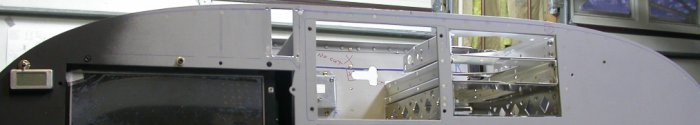 The blue line at the top of the panel shows where the round tubing part of
the canopy frame overlaps the instrument panel. It tapers up for less
overlap at each end. Be sure to keep this overlap in mind as you plan
your panel!
The blue line at the top of the panel shows where the round tubing part of
the canopy frame overlaps the instrument panel. It tapers up for less
overlap at each end. Be sure to keep this overlap in mind as you plan
your panel!
![]() The out-of-focus picture actually showed the depth and interference better
than an in-focus pic did. The optional canopy brace practically lays
on the top of the Garmin GMA340 audio panel tray and may further reduce
clearance at the back to the tray.
The out-of-focus picture actually showed the depth and interference better
than an in-focus pic did. The optional canopy brace practically lays
on the top of the Garmin GMA340 audio panel tray and may further reduce
clearance at the back to the tray.
March 15 - more planning wire runs between front and rear of plane. I asked Van's about cutting any more holes in the spar for wiring, and they said this: If you review DWG 11, notice the callout for the 5/8" dia holes with the SB625-7 snap bushings in them. You can replicate this same thing in the web of the F-704A & B as shown in the DWG. Be aware that you want to maintain adequate hole edge distance from any other holes, and to also maintain adequate distance from the F- 704E & F center section bars. You could add a couple more pass throughs if needed. For the rear spar pass through, review DWG 20 for the appropriate locations. Thanks Joe To get between the front and back, I will use thin wall aluminum tubing (not the PVC tubing I hear some people use!) to go under the LT seat and LT baggage floor. 0.5 hr + 1.0 hr doc
March 16 - ordered tubing for under-floor conduit from ACS. Drill holes in fuselages side ribs for battery wires. Prep battery wires for threading by installing nylon spiral wrap and heatshrink tubing. 0.75 hr
March 17 - finish prepping battery wires for threading, start threading battery wires from the contactors back to the battery area, behind the LT baggage compartment. 3.25 hr
March 18 - finish threading battery wires - tight fit between wires (covered with nylon spiral wrap, then heatshrink) and plastic bushings made this a long, slow process. Install battery wires end terminals. Screw around with switches panel mount studs. Cut off one mount stud. Rework nutdriver on lathe to try to get access to switches panel mount nuts. The big problem is that, when I put the captive studs into the bottom of the panel, to hold the switches panel in place, I did not think to space them between the switches. Big mistake - I may even have to redo the switches panel because of that. I can probably get locknuts on (just using plain nuts for now), but it'll be so much trouble to get them on and off that it'll negate any value of making the switches panel removable - I might as well have saved a lot of trouble and just riveted the switches panel to the instrument panel. 3.25 hr
March 19 - got my GRT order with ARINC-429 connector, GRT internal GPS, and supercharger pressure transducer. Lots of misunderstandings with all this, so I will call GRT tomorrow. Apparently Sandy didn't understand what connector I was referring to when I talked to her on the 9th about the ARINC-429 connectors. She thought I was referring to the DB-9 connector, when I'd been referring to the odd flat connectors on what I called the back of the module. My ARINC-429 module had come with no instructions, so I'd assumed it was a standalone module (see how I mounted it March 10). Well, the GPS came with instructions, and those instructions say the GPS and ARINC-429 modules are exactly the same external box, so they mount the same. It turns out that the GPS and/or ARINC-429 mount directly to the display motherboard. The odd connectors on the back of the modules actually plug into pins on the display motherboard. So, since I only have ONE display, I only have ONE place to mount one module or the other. GRT really ought to combine these 2 modules or make one or both standalone.
Also, the "supercharger pressure" module I got in my order is actually the same as the MAP sensor I already have installed. It looks like it's made more for reading vacuum, not pressure. The hose fitting on it is rather recessed, so I'm concerned that a pressure application would blow the hose off, since I can't get a clamp onto it. I also don't want to run a pressure line into the cabin. I was thinking much more along the lines of a transducer like the VDO fuel pressure transducer; something that screws directly into the pressurized place to be measured, with only wires running back to the EIS.
March 20 - talked to Sandy and Carlos at GRT. They said I should return the GPS module and I'd have to plan to use the GPS from my Garmin 496 instead. Sandy is looking into what I should be using to monitor supercharger pressure. I still think it should be their 0-30 psi VDO fuel pressure sensor.
March 21 - got a call from Sandy at GRT. They agree that the best thing for my supercharger pressure monitoring is the fuel pressure sender, so she is sending that to me today. I am returning the GPS module and the MAP sensor. I also suggested to her that GRT consider making it possible to use both the ARINC-429 and GPS modules with one display; either by combining the 2 modules onto one board, or by making one of them able to be installed standalone (not plugged directly into a display). If you have or plan to have one GRT display and would like to use both the ARINC-429 and GPS modules, you might also suggest this change to GRT, as more demand will make it more likely to happen. I haven't gotten out to work on the plane the last 2 evenings. Received order from ACS, with the thin wall 3/4" aluminum tubing I plan to use for conduit under the LT cabin and baggage compartment floors. Worked on cutting holes in LT baggage floor for access under baggage compartment and cutting holes in LT baggage floor ribs for the conduit. Started installing Adel clamps for the conduit. 2.25 hr
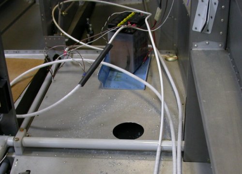
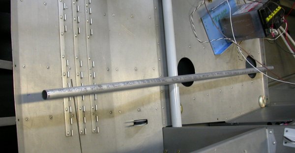 This pic shows the planned layout (under the floors) of the conduit.
The two 3" holes I drilled into the baggage floor give me access to the
baggage floor ribs. They will be covered by access plates later.
This pic shows the planned layout (under the floors) of the conduit.
The two 3" holes I drilled into the baggage floor give me access to the
baggage floor ribs. They will be covered by access plates later.
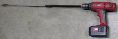
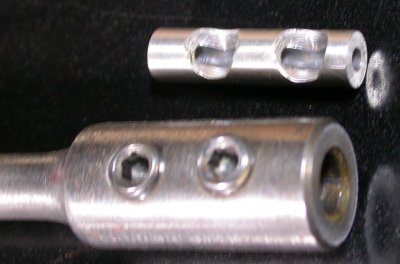 I needed a drill at least 2' long to get from the 7/8" hole I made in the
aft baggage compartment floor rib to the middle rib. The standard
drill extensions are made for a 1/4" shank. So, I used the lathe and
mill to make this little adapter to let me use a 12" #40 bit in the 1/4" ID
extension. I needed to start the hole with a small bit because I was
not able to attack the rib from a 90 degree angle, and there's no way a
Unibit would have started a hole where I needed it, without a starter hole.
I needed a drill at least 2' long to get from the 7/8" hole I made in the
aft baggage compartment floor rib to the middle rib. The standard
drill extensions are made for a 1/4" shank. So, I used the lathe and
mill to make this little adapter to let me use a 12" #40 bit in the 1/4" ID
extension. I needed to start the hole with a small bit because I was
not able to attack the rib from a 90 degree angle, and there's no way a
Unibit would have started a hole where I needed it, without a starter hole.
 Then, I needed a bigger extension to handle the 3/8" shank on the big 7/8"
Unibit to enlarge the hole for the conduit, so I pieced together
large-diameter 12" and 15" extensions to get that done.
Then, I needed a bigger extension to handle the 3/8" shank on the big 7/8"
Unibit to enlarge the hole for the conduit, so I pieced together
large-diameter 12" and 15" extensions to get that done.
March 22 - make covers for the two 3" access holes I cut in the baggage compartment floor. Lay out & install cover nutplates. Install & clamp conduit. Ponder more wiring routing. 2.75 hr
March 23 - prime & paint baggage compartment access covers. See HERE for summary on the baggage compartment flooor panels & conduit. Wire redone fuel pressure sender. Ponder warning lights choices & layout. Wasted a bunch of time looking for several things. Finally found 2 of the 3 things. Experiment with various LEDs for use as indicators. 1.25 hr
Mar 25 - mostly wasting time; didn't actually "accomplish" anything. Still looking for my AirGizmos angle mount adapter. Farted around pondering my indicators panel and which indicators to use. Experimented with various LEDs. Finally decided on diffused flashing red 5mm with 390 ohm for low fuel pressure, diffused green/yellow 5mm with 620 ohm for aux fuel pump, and diffused red 5mm for LVWAABMM warning. Mostly decided on EIS warning lamp, but I had a question about it for Eggenfellner before I cut the hole for it. 3.0 hr
 LEDs
are super for indicators, as well as for lighting. You can get all
sorts of sizes, colors, brightness, primary viewing angle, etc.
You can also get flashing ones and ones that can produce 2 different colors.
They're easily dimmable, take very little panel space, take next to no
current, quite durable (no filament to break from vibration), and will last
forever. They are also quite inexpensive, especially when purchased as
just a standalone LED (as opposed to a premade LED indicator). The
brighter ones, though, suffer from "LED glare" when used as a panel
indicator. If you're offset from the primary intensity angle, they
don't show up that well. If you're in the primary intensity angle,
they can be quite glaring, especially the brighter ones (ever look directly
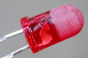
into an LED flashlight?). You can also buy diffused LEDs, but it's
easy to diffuse any LED that's too glary. Just scratch up the plastic
some with fine sandpaper, as shown in this pic. That kills the glare
zone directly in front of the LED and it also diffuses the light evenly
throughout the scratched area, so you get the same brightness from all
angles. I chucked this up (gently) in my battery drill and spun it
slowly while holding the sandpaper to it. Works great. Scuff the
whole area of the LED that will be exposed from your panel.
LEDs
are super for indicators, as well as for lighting. You can get all
sorts of sizes, colors, brightness, primary viewing angle, etc.
You can also get flashing ones and ones that can produce 2 different colors.
They're easily dimmable, take very little panel space, take next to no
current, quite durable (no filament to break from vibration), and will last
forever. They are also quite inexpensive, especially when purchased as
just a standalone LED (as opposed to a premade LED indicator). The
brighter ones, though, suffer from "LED glare" when used as a panel
indicator. If you're offset from the primary intensity angle, they
don't show up that well. If you're in the primary intensity angle,
they can be quite glaring, especially the brighter ones (ever look directly
into an LED flashlight?). You can also buy diffused LEDs, but it's
easy to diffuse any LED that's too glary. Just scratch up the plastic
some with fine sandpaper, as shown in this pic. That kills the glare
zone directly in front of the LED and it also diffuses the light evenly
throughout the scratched area, so you get the same brightness from all
angles. I chucked this up (gently) in my battery drill and spun it
slowly while holding the sandpaper to it. Works great. Scuff the
whole area of the LED that will be exposed from your panel.
QUICK LED PRIMER: don't know much about using LEDs? It's really very simple. You can get all sorts of them at Radio Shack, as well as any electronics place. You have to use a resistor in series with them. If you don't know which resistor to use, about 500 ohms will be OK for most everything. Or you can get precise values by clicking here. Polarity DOES matter, though. The longer leg is the + side, and/or the little flat on the side of the LED is the negative side. The resistor can go anywhere in the + or - circuit. Get to know LEDs - you can't beat them for lighting and/or your indicators. You even see lots of them on the road on cars and trucks now, and Bill VonDane's CreativeAir site now carries LED aircraft navigation lights. SteinAir has several good LED-based lights and indicators, although I thought their indicators were a tad glary, if they're going to be directly in front of you. Radio Shack has little plastic snap-in bushings that let you mount the LED in your panel. They also have fancier metal mounts that fasten to the panel with a nut. Spend a couple bucks at Radio Shack, buy a few LEDs & resistors, and play with them. You'll see what I mean.
March 26 - update web site 2.0 hr doc
March 27 - did some more indicators pondering, then got down to business. Cut holes for and installed low coolant level, L & R low fuel level, EIS warning, low fuel pressure, and "aux pump on" indicators.
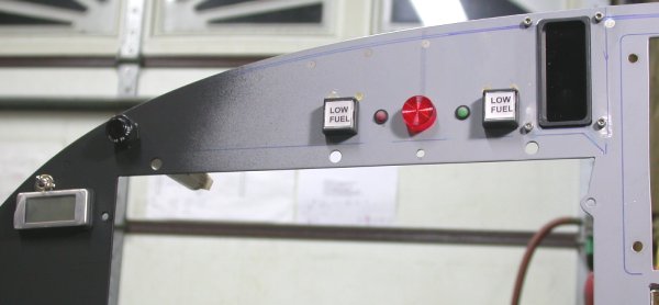 Here
are my indicators, temporarily installed. Far LT is the DVM and its
battery selector switch. On the RT of that is the Gary Newsted low
coolant level indicator and module, rather hard to see because of the
black-on-black. You can see the LT & RT low fuel level warning
indicators. In the pilot's centerline, indicated by the faint heavy
blue vertical line under the primer, is the big red EIS warning light.
To the LT of that is the red flashing LED for low fuel pressure. To
the RT of the EIS warning light is the green/yellow LED to indicate the aux
fuel pump is on. To the RT of the aux pump LED is the Angle of Attack
display. I still need to do the LVAABMM low voltage warning LED,
either just to the LT or RT of the low coolant indicator. The big hole
under the indicators is for the Blue Mountain EFIS/One, and the hole in the
upper RT is for the Grand Rapids Technologies Horizon EFIS. The rest
of the space in the triangle above the BMA EFIS is reserved for future
indicators expansion. The bottoms of the low fuel indicators barely
clear the top of the BMA EFIS display. Everything is shoved as far as
possible to one side or the other, to leave as much space as possible for
anything I may have overlooked so far. It's only a few indicators, but
it seems to cover everything I can think of so far. The whole panel
will be painted flat black, as on the LT, when I am done cutting holes in
it.
Here
are my indicators, temporarily installed. Far LT is the DVM and its
battery selector switch. On the RT of that is the Gary Newsted low
coolant level indicator and module, rather hard to see because of the
black-on-black. You can see the LT & RT low fuel level warning
indicators. In the pilot's centerline, indicated by the faint heavy
blue vertical line under the primer, is the big red EIS warning light.
To the LT of that is the red flashing LED for low fuel pressure. To
the RT of the EIS warning light is the green/yellow LED to indicate the aux
fuel pump is on. To the RT of the aux pump LED is the Angle of Attack
display. I still need to do the LVAABMM low voltage warning LED,
either just to the LT or RT of the low coolant indicator. The big hole
under the indicators is for the Blue Mountain EFIS/One, and the hole in the
upper RT is for the Grand Rapids Technologies Horizon EFIS. The rest
of the space in the triangle above the BMA EFIS is reserved for future
indicators expansion. The bottoms of the low fuel indicators barely
clear the top of the BMA EFIS display. Everything is shoved as far as
possible to one side or the other, to leave as much space as possible for
anything I may have overlooked so far. It's only a few indicators, but
it seems to cover everything I can think of so far. The whole panel
will be painted flat black, as on the LT, when I am done cutting holes in
it.
It was an awful lot of planning and work to just drill a few holes, but it was very important to me to get the indicators right. After all, the indicators are my interface with any problems that occur, and I want that interface to be as perfect as I can get it; clear, unambiguous, hard to miss but not blinding, enabling instant recognition of problem in daylight or darkness, etc.
March 28 - locate & drill hole for low voltage indicator, just to RT of low coolant indicator. Drill out 3 of the 4 captive studs for attaching the switches panel to the instrument panel. Install 2 new captive studs in locations BETWEEN the switches, as I should have done it in the first place. Assemble panel, indicators, BMA display. Spent some time looking for the best place to install the two Angle of Attack pushbutton switches. Also talked to Eckhard again about my Garmin avionics. Apparently he didn't order them when I asked him to earlier in the month, so I reminded him again of what I need, and he will get them this week. 4.0 hr
March 29 - found out the source of the EIS warning light - GRT, not Eggenfellner, supplied it, and it comes from Radio Shack. It doesn’t have a replaceable bulb, so I’ll need to know where I can get another one like it. It has a larger-than-average diameter, so I wouldn't be able to replace it with some other indicator if it goes bad. I looked it up on Radio Shack's web site and it is Model: 272-336 Catalog #: 272-336, 9/16" hole, pack of 2 for $3.29. Did final test of warning indicators, both with the garage lights on and with them off, to make sure they were eye-catching enough in the light and not blinding in the dark. Located & drilled holes for AoA switches. I may have gotten one of the AoA switches a tad high, but I think it'll be barely OK (regarding clearance above to the canopy frame glare shield support rod). Removed all indicators & instruments, removed panel, removed all trays. Epoxied spacer shims onto SL-30 tray for proper fit to Garmin trays. Scuff, clean, and paint panel. 2.5 hr
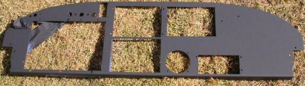 Here's the panel, all painted. It's flat black for several reasons.
It's very easy to paint or to touch up the paint and leave no trace of the
touchup. It will easily blend into the display bezels and background.
After all, I don't want to see the panel; I want to see the instruments
mounted on it. This leaves the focus on the displays and indicators.
I may need to add some stuff on the RT side, and I still need to do the air
vents, but this should cover it for now. Once I solder up the LED
indicators, I don't want to remove them.
Here's the panel, all painted. It's flat black for several reasons.
It's very easy to paint or to touch up the paint and leave no trace of the
touchup. It will easily blend into the display bezels and background.
After all, I don't want to see the panel; I want to see the instruments
mounted on it. This leaves the focus on the displays and indicators.
I may need to add some stuff on the RT side, and I still need to do the air
vents, but this should cover it for now. Once I solder up the LED
indicators, I don't want to remove them.
March 31 - Talked with Eckhard about avionics. Looked into getting AirGizmos Garmin 496 adapter either into the GNS 530 tray slot or into the 530 tray itself. Ended up drilling out one lower nutplate rivet on each side of tray mount brackets. Received 0-30 psi pressure sender from GRT. 1.0 hr
Go to APRIL, 2007 avionics page
BACK TO MY RV BUILDER'S HOME
BACK TO BRIAN'S HOME