 This is an old pic of how I had planned to mount the AoA display, hanging
from the glare shield, as there seemed to be no room to mount it in the
panel; at least not in the center, where I need it to be.
This is an old pic of how I had planned to mount the AoA display, hanging
from the glare shield, as there seemed to be no room to mount it in the
panel; at least not in the center, where I need it to be.FEBRUARY, 2007 AVIONICS, ELECTRICS, & CONTROLS
If it's general supporting wiring, it's on this page. If it's strictly engine wiring, it's on the engine page, so be sure to check there for details.
Feb 1 - it's been quite cold - will try to get back out in the garage ASAP. Also been busy getting taxes done and doing all the paperwork and planning for my hangar. I emailed Eckhard about a week ago to start moving forward in my panel, but no response. I will have to ping him again soon.
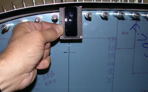
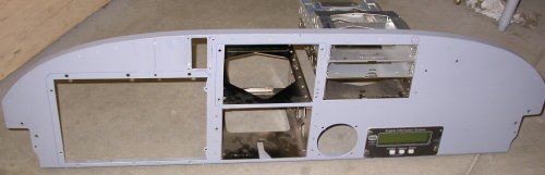
Feb 3 - after reviewing the indicators layout I've been working on lately, I decided that perhaps I could fit the Angle of Attack (AoA) display into my panel, after all. I had wanted it to be centered in my upper field of view, and there was no room for it in the panel, so I had planned to suspend it from the glare shield. After I did the indicators layout in TurboCAD, I realized I might be able to squeeze it into my planned "indicators" space. I determined it would barely fit, so I laid the panel out for the hole and cut the hole. It is a perfect fit. After various trimming, it hits other things on 3 sides, but it does fit in there snugly. This is a much better location for it than hanging down from the canopy glare shield. 4.0 hr
This is an old pic of how I had planned to mount the AoA display, hanging
from the glare shield, as there seemed to be no room to mount it in the
panel; at least not in the center, where I need it to be.
 This
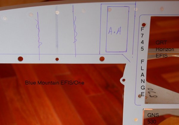
is the new layout for the Angle of Attack display. I had planned to
suspend it from the glare shield, directly in front of the pilot's line of
sight, indicated by the heavy vertical line showing through the primer here.
I had planned to lay out the warning indicators on either side of it, as
indicated by the blue lines crossed out. To put it in the panel here would mean a very tight
fit, and having to remove a couple rivets and cut away part of the leg for
the upper panel support angle, but it seemed feasible, so I proceeded.
You can see how tight it would be. On the RT, it's right up against
the F745L, which is also the LT mounts for the GRT EFIS. On the top,
it's right up against the angle. On the bottom, it's touching the top
of the BMS EFIS display bezel.
This
is the new layout for the Angle of Attack display. I had planned to
suspend it from the glare shield, directly in front of the pilot's line of
sight, indicated by the heavy vertical line showing through the primer here.
I had planned to lay out the warning indicators on either side of it, as
indicated by the blue lines crossed out. To put it in the panel here would mean a very tight
fit, and having to remove a couple rivets and cut away part of the leg for
the upper panel support angle, but it seemed feasible, so I proceeded.
You can see how tight it would be. On the RT, it's right up against
the F745L, which is also the LT mounts for the GRT EFIS. On the top,
it's right up against the angle. On the bottom, it's touching the top
of the BMS EFIS display bezel.
 Using the template provided with the AoA system to lay out the mounting
holes and the display cutout. You can see how close it is to the
stiffening angle on top and the BMA display outline (blue line) on the
bottom.
Using the template provided with the AoA system to lay out the mounting
holes and the display cutout. You can see how close it is to the
stiffening angle on top and the BMA display outline (blue line) on the
bottom.
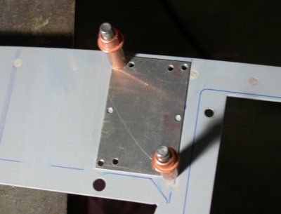
 Here, in the back of the panel, I have removed the stiffening angle leg that was in the
way. It was tricky cutting. First, I drilled out the 2 rivets.
Then I used a 3" cutoff wheel in my
battery drill to carefully cut through about 90% of the vertical leg.
Then I
used my pocket knife to bend the leg out and break it off. Then I used
a flat-ended carbide rotary file in my Dremel tool to trim the vertical
angle leg back flush with the horizontal angle leg, all without cutting into
the instrument panel. I also had to trim the upper LT corner of the AoA display, so it would all fit in here. The red
line on the LT (in pic) is where the F745L goes, mounting both the panel to
the F745L and
the GRT EFIS display to the panel. The blue line on the bottom is the top of the
Blue Mountain EFIS display bezel.
Here, in the back of the panel, I have removed the stiffening angle leg that was in the
way. It was tricky cutting. First, I drilled out the 2 rivets.
Then I used a 3" cutoff wheel in my
battery drill to carefully cut through about 90% of the vertical leg.
Then I
used my pocket knife to bend the leg out and break it off. Then I used
a flat-ended carbide rotary file in my Dremel tool to trim the vertical
angle leg back flush with the horizontal angle leg, all without cutting into
the instrument panel. I also had to trim the upper LT corner of the AoA display, so it would all fit in here. The red
line on the LT (in pic) is where the F745L goes, mounting both the panel to
the F745L and
the GRT EFIS display to the panel. The blue line on the bottom is the top of the
Blue Mountain EFIS display bezel.
Feb 4 - trim AoA hole, reinstall removed rivet, check AoA fit OK. Make pen changes to indicators panel drawing. Bitter cold out - single digits - so the 250K BTU heater was going full blast the whole time for the last couple days' work. 1.0 hr
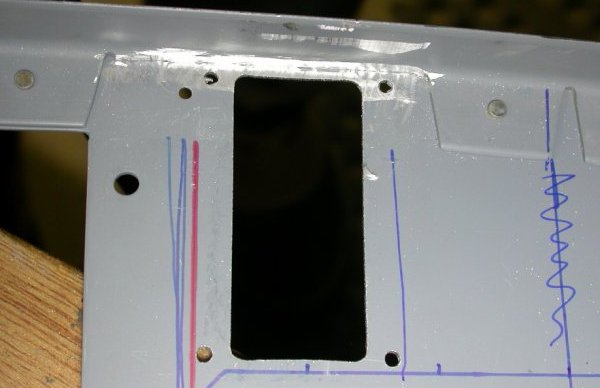
 This shows how tight the AoA display fit is; tight up against the top angle
(I even had to round off the upper LT [RT in pic] of the display to get it
to fit) , tight against the red line on the LT marking the edge of the F745L
flange, and tight against the blue line on the bottom marking the top of the
BMA EFIS display bezel. Everything in my instrument panel is a "just
barely fits"
snug fit. The fit of the bottom of the BMA display to the bottom of
the instrument panel is just as tight. I later filled in the removed rivet hole in the upper LT of pic with
a dummy rivet; again, barely clearing the AoA display.
This shows how tight the AoA display fit is; tight up against the top angle
(I even had to round off the upper LT [RT in pic] of the display to get it
to fit) , tight against the red line on the LT marking the edge of the F745L
flange, and tight against the blue line on the bottom marking the top of the
BMA EFIS display bezel. Everything in my instrument panel is a "just
barely fits"
snug fit. The fit of the bottom of the BMA display to the bottom of
the instrument panel is just as tight. I later filled in the removed rivet hole in the upper LT of pic with
a dummy rivet; again, barely clearing the AoA display.
 And here is the instrument panel after adding the AoA display. Now, I
need to redo my "indicators" drawing and continue laying out my warning
indicators, using the little triangle to the left of the AoA display and
above the BMS EFIS display.
And here is the instrument panel after adding the AoA display. Now, I
need to redo my "indicators" drawing and continue laying out my warning
indicators, using the little triangle to the left of the AoA display and
above the BMS EFIS display.
Feb 5 - still bitter cold & predicted to remain that way. Worked on updating indicators layout in TurboCAD. 1.5 hr
Feb 9 - TurboCAD work on warning/indicators layout. Also talked to Eckhard some about proceeding with Garmin wiring. It's so cold, he isn't doing much, either. 1.0 hr
Feb 26 - more people on the GRT list are saying the GRT Hall Effect current sensor is wildly inaccurate and changing values all over the place. I need to test mine soon, the next time I run the engine. See previous entry in November about this issue.
Feb 27 - Spent some time configuring the Grand Rapids EIS4000 and documenting my settings. What an incredibly cumbersome thing to program! All access is serial; you enter the setup menu, then press "next" to proceed to the next item. The only way to get to any item is to keep pressing the "next" button until you get to it, even if it's the very last item in the string. There is no "back" key or "exit" key - if you miss something, you go serially all the way through dozens of pages to the end, then back around again. Same thing for entering values once you get to the entry you want. Want a value to be "150"? Well, just press the "up" button a mere 150 times. Repeat a few dozen times, for each entry. Jeeez! I need to write to GRT and suggest a better access method, such as a computer interface and/or a text lookup table for these values. While my Aux5 (current) was highly inaccurate (reading 105 amps), it was steady and slowly dropped to an indicated 102 amps, so I did not see the wildly fluctuating values reported by others on the GRT list. Now, I just need to get the proper config values for that port, so the reading is accurate. MARCH UPDATE- I later found out that, if you hold an EIS button down, it will repeat rapidly, saving all that tedious button pushing. 1.5 hr
Feb 28 - emailed Sandy at Grand Rapids to find out suggested starting values for their current sensor I have on AUX5 of the EIS. Got a quite prompt reply with this info:
5SF 186
5OFF 357
then, if you need to adjust ... for every 1 off on the aux5 reading change the OFF by 2. example if you're reading 4 when it should read 1, (3x2=6) change the offset by 6
Worked on more EIS programming. Set up EIS AUX5 as above (pressing a button some 600 times to put in the 2 above values). Put an analog amp meter in series with the alternator B cable, ran the engine, and tested the AUX5 (amps) readout. It was reading a couple amps high at first, but then it settled down into reading the same as the analog meter. The reading was always steady, so it seems like that setup is good to go. 1.0 hr
GO TO MARCH, 2007 AVIONICS/ELECTRICAL PAGE
BACK TO MY RV BUILDER'S HOME
BACK TO BRIAN'S HOME