A lot of what I am doing right now is wiring related toward
getting the engine ready to start. If it's strictly engine wiring, it
on this page. If it's more general supporting wiring, it's on the
avionics/electric page, so be sure to check there for details.
I am also working on the console on the fuselage
page.
Dec 1 - fit electronic throttle
mount to quadrant 3.0 hr
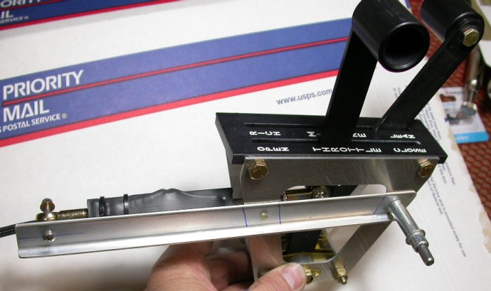
This is the mount system for the electronic throttle. The angle
bracket is placed so its centerline is the same as the centerline of the
travel path of the clevis, hence the bracket is not parallel with the top of
the quadrant. That's because the lever does not travel the full length
of the slot - it travels the length of the slot minus the width of the
lever. The linkage is carefully placed to give me exactly 2" of travel
of the transducer rod. The transducer rod has about 2 1/8" of travel,
so I adjusted the mounting and transducer rod clevis end so there is 1/16"
of transducer travel left beyond each throttle stop.
Dec 2 - finish quadrant throttle
mount, work on wastegate control mount layout
2.25 hr
Those captive studs I got for mounting
the switches panel to the instrument panel sure work great here on the
quadrant for mounting the brackets.
Dec 3 - work on throttle quadrant
wastegate control mount. Fabricate & TIG weld quadrant wastegate
control mount bracket. Fine-tune and final-adjust electronic throttle
mount. 4.75 hr
Here is the quadrant with the electronic throttle transducer module
final-mounted on the back side of the quadrant, and waiting now for more TIG
welding on the wastegate control mount bracket, which will go on this side
of the quadrant. I don't want the wastegate travel to be linear with
the throttle travel (I want it to open as quickly and fully as possible as
soon as the throttle starts to close), so the clevis for the wastegate
control is mounted as high as possible on the RT lever. Also, the
wastegate control needs to travel only 1.5" (vs 2" for throttle), so the
correct bracket mount angle is different for the wastegate control than it
is for the throttle. The vertical marks on the top of the quadrant
show the lever travel for the center of the wastegate clevis, measured both
perpendicular to the top of the quadrant and parallel to the lever
centerline. Once I get the wastegate control fully adjusted, I will
install a lever stop at the aft end of the abbreviated wastegate control
lever travel.
Dec 4 - Finish TIG welding
wastegate control mount bracket. Update web site
2.0 hr + 1.0 hr doc
Dec 5 - Ream Bowden cable clamp to
fit cable. Back to console work
0.5 hr
Here is the quadrant with the TIG-welded bracket for the Bowden cable clamp,
in the background. The electronic throttle mount is in the foreground.
Dec 7 - remember Pearl Harbor!
Dec 10 - I've been getting
nervous about how long it's been trying to get the engine ready to
start, and worrying that rust or corrosion could form inside the engine
from sitting so long. Each month, I think I'll be starting the
engine this month, but it hasn't happened yet. Got some
engine fogging oil and removed coils and spark plugs. Sprayed
fogging oil into cylinders. 0.75 hr
Dec 14 - buy some 5w-30 oil and
put 4.5 qt into engine. Theoretically, that should have filled it, as
the spec is 4.8 and the filter is already filled. The stick showed way
overfull, but as soon as I start the engine, the oil cooler will fill, so
that's about another quart right there. Hook up starter switch.
0.5 hr
Dec 16 - After getting the
batteries and contactor switch wired,
removed spark plugs , powered up contactor and spun engine over a few times, to
spread the fogging oil I had sprayed into the cylinders.
Dec 17 - more vacuum line routing and
installing Adel clamps to hold the line 0.75
hr
Dec 18 - Cut throttle wires to
length and install machined gold crimp pins. Update web site
0.5 hr + 1.0 hr doc
Dec 19 - finished making DB-9 connector for
throttle. Plugged in throttle, connected ECM switch, powered up ECM for
the first time. Throttle seems to actuate perfectly with the throttle
lever. One thing I noticed is that, when closing the throttle, the
last 1/8” of lever travel does not cause any additional butterfly travel; the
butterfly is fully closed when the throttle lever is 1/8” from the stop.
When opening the throttle, full throttle butterfly opening is achieved when the
lever is 5/8” before the stop. In other words, the last 5/8” of lever travel
does not cause any more butterfly travel, because the butterfly is already fully
open. This will actually prove beneficial to me, regarding the manual
wastegate control. When both levers are fully fwd and I pull them back as
one, the levers will actually travel 5/8” before the throttle butterfly starts
closing, giving me that much more early wastegate opening travel as the throttle
butterfly starts to close. All I have to do now is finalize a few
details on the fuel plumbing, check for plumbing leaks, and the engine will be
ready to start. 1.0 hr
Dec 21 - One problem I had with my fuel return
plumbing is that I had decided to use a bulkhead fitting at the side of the
fuselage. The problem is that the fuselage is dual wall right there,
with a gap between the 2 walls. So, I can't tighten up the bulkhead
fitting nut without squeezing the 2 pieces of metal together. It's a
Quick Build, so it's all riveted together already. I couldn't figure
out how I was going to fix that, but I ended up getting some paste epoxy and
pushing it in between the inner and outer skins.
1.0 hr
This pic shows the gap between the fuselage skin and the two brace pieces on
the inboard. This is fwd of the wing spar holes and aft of the
larger hole for the fuel feed line. This will have a bulkhead fitting
for the fuel return line required by automotive fuel injection systems.
The epoxy paste I was able to stuff into the gap between the skins will keep
the bulkhead fitting nut from squeezing the 2 pieces of metal together.
The outer skin is a little scarred up from my previous attempts to get the
AN bulkhead fitting nut tight without anything between the 2 sheets, but
that will polish out. Also, a closeup pic like this tends to
exaggerate how badly it's scratched. It's kinda cold in the garage, so
this epoxy is setting rather slowly, but it is setting up hard after a
couple days.
 This is the mount system for the electronic throttle. The angle
bracket is placed so its centerline is the same as the centerline of the
travel path of the clevis, hence the bracket is not parallel with the top of
the quadrant. That's because the lever does not travel the full length
of the slot - it travels the length of the slot minus the width of the
lever. The linkage is carefully placed to give me exactly 2" of travel
of the transducer rod. The transducer rod has about 2 1/8" of travel,
so I adjusted the mounting and transducer rod clevis end so there is 1/16"
of transducer travel left beyond each throttle stop.
This is the mount system for the electronic throttle. The angle
bracket is placed so its centerline is the same as the centerline of the
travel path of the clevis, hence the bracket is not parallel with the top of
the quadrant. That's because the lever does not travel the full length
of the slot - it travels the length of the slot minus the width of the
lever. The linkage is carefully placed to give me exactly 2" of travel
of the transducer rod. The transducer rod has about 2 1/8" of travel,
so I adjusted the mounting and transducer rod clevis end so there is 1/16"
of transducer travel left beyond each throttle stop.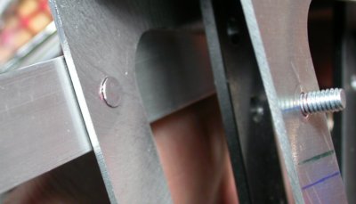 Those
Those 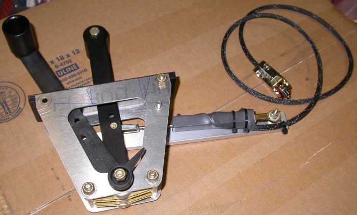 Here is the quadrant with the electronic throttle transducer module
final-mounted on the back side of the quadrant, and waiting now for more TIG
welding on the wastegate control mount bracket, which will go on this side
of the quadrant. I don't want the wastegate travel to be linear with
the throttle travel (I want it to open as quickly and fully as possible as
soon as the throttle starts to close), so the clevis for the wastegate
control is mounted as high as possible on the RT lever. Also, the
wastegate control needs to travel only 1.5" (vs 2" for throttle), so the
correct bracket mount angle is different for the wastegate control than it
is for the throttle. The vertical marks on the top of the quadrant
show the lever travel for the center of the wastegate clevis, measured both
perpendicular to the top of the quadrant and parallel to the lever
centerline. Once I get the wastegate control fully adjusted, I will
install a lever stop at the aft end of the abbreviated wastegate control
lever travel.
Here is the quadrant with the electronic throttle transducer module
final-mounted on the back side of the quadrant, and waiting now for more TIG
welding on the wastegate control mount bracket, which will go on this side
of the quadrant. I don't want the wastegate travel to be linear with
the throttle travel (I want it to open as quickly and fully as possible as
soon as the throttle starts to close), so the clevis for the wastegate
control is mounted as high as possible on the RT lever. Also, the
wastegate control needs to travel only 1.5" (vs 2" for throttle), so the
correct bracket mount angle is different for the wastegate control than it
is for the throttle. The vertical marks on the top of the quadrant
show the lever travel for the center of the wastegate clevis, measured both
perpendicular to the top of the quadrant and parallel to the lever
centerline. Once I get the wastegate control fully adjusted, I will
install a lever stop at the aft end of the abbreviated wastegate control
lever travel.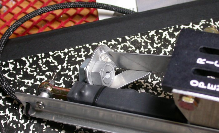 Here is the quadrant with the TIG-welded bracket for the Bowden cable clamp,
in the background. The electronic throttle mount is in the foreground.
Here is the quadrant with the TIG-welded bracket for the Bowden cable clamp,
in the background. The electronic throttle mount is in the foreground.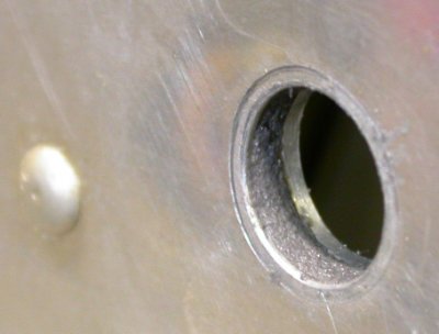 This pic shows the gap between the fuselage skin and the two brace pieces on
the inboard. This is fwd of the wing spar holes and aft of the
larger hole for the fuel feed line. This will have a bulkhead fitting
for the fuel return line required by automotive fuel injection systems.
The epoxy paste I was able to stuff into the gap between the skins will keep
the bulkhead fitting nut from squeezing the 2 pieces of metal together.
The outer skin is a little scarred up from my previous attempts to get the
AN bulkhead fitting nut tight without anything between the 2 sheets, but
that will polish out. Also, a closeup pic like this tends to
exaggerate how badly it's scratched. It's kinda cold in the garage, so
this epoxy is setting rather slowly, but it is setting up hard after a
couple days.
This pic shows the gap between the fuselage skin and the two brace pieces on
the inboard. This is fwd of the wing spar holes and aft of the
larger hole for the fuel feed line. This will have a bulkhead fitting
for the fuel return line required by automotive fuel injection systems.
The epoxy paste I was able to stuff into the gap between the skins will keep
the bulkhead fitting nut from squeezing the 2 pieces of metal together.
The outer skin is a little scarred up from my previous attempts to get the
AN bulkhead fitting nut tight without anything between the 2 sheets, but
that will polish out. Also, a closeup pic like this tends to
exaggerate how badly it's scratched. It's kinda cold in the garage, so
this epoxy is setting rather slowly, but it is setting up hard after a
couple days.