Mar 1 - getting LT flap installed. Visit from Bud
Bushway from local EAA Chapter 740. Metal prep and
prime LT flap brace. 4.5 hr
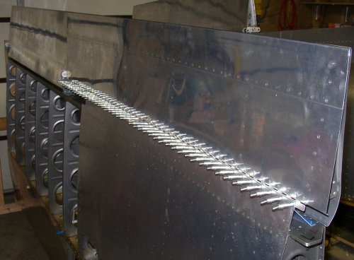
Here is the
LT flap clecoed into place. The blue piece you can see in front of the
row of clecoes is the flap brace, which also gets clecoed and riveted in
here. This was rather time-consuming, as it was very difficult to get
the flap positioned just right to match the height and line of the
aileron. The problem was that the flap leading edge hit the clecoes
holding the flap brace in place, so that tended to move things around as I
was trying to get it set up. Also, the hinge had no holes, so it had
to be held with a side clamp, not a cleco, and so the flap brace kept moving
out of its hole alignment with the lower skin. After trying a couple
techniques, I finally got it where I wanted it. I match-drilled just
the skin and brace, then added the flap and used a rivet through the skin
and brace to hold them in alignment while I got each end of the flap positioned both
horizontally and vertically with side clamps.
Mar 2 - rivet LT flap and flap brace. Start installing
RT flap. Metal prep and prime RT flap brace. 5.5
hr
Here is
the LT flap brace and flap hinge, after all the metal prep work and priming
the brace.
Here is a
refined use of the technique I invented, which I call double-dimpling.
I started doing it to better match 2 dimpled skins when I was doing the tail
at Alexander Technical Center. Here, I am using it to make a much better fit among the lower
skin, flap brace, and flap hinge. I dimpled the skin and brace, and
countersunk the hinge, but there's no way a dimple will properly sit in a
hole countersunk for a rivet head. This is because the skin thickness
of a dimple makes the outside of the dimple (the part that will sit in
another dimple or in a c/s hole) much bigger than a 426-3 rivet head.
Also, if you think about it, if you use a die to make 2 parts, then the 2
parts (dimples, in this case) will be identical. So, if you have 2
identical parts (dimples), then one is NOT going to nest nicely inside the
other. So, after dimpling the skin and brace and countersinking the hinge, I then squeezed it
all together and forced the metal into a much better fit, by using the dimple
die to squeeze all 3 pieces at once. This forced the 2 dimpled parts
into a much tighter fit, and then squeezed all that into the countersink in
the hinge. I was very satisfied with the results after doing
this. As you can see, the 3 pieces fit very tightly together where the
squeezer is, but not as tight where the cleco is. I would have
otherwise had to make the countersink much bigger to get the dimples to sit
in them properly. After doing the double dimpling, I squeezed all these
rivets. The plans called for a 426-3-4, but I found the -4.5 was a
better fit, so I used those.
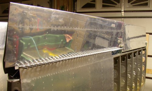
Here is the
RT flap clecoed into place. I was able to do the RT flap much more
quickly, with less fooling around, than the LT one. I got the flap
brace all prepped and primed. Tomorrow, after the primer has dried
overnight, I will install and rivet the RT flap.
Mar 3 - riveted RT flap into place. I wasn't sure what
to work on next, so I decided to put in the landing lights. Flipped LT
wing over and started on landing light. Upon opening the wing light
package, I realized there was a 100 watt upgrade available from the
manufacturer (not Van's), so I called Duckworks, the mfg, and ordered the
upgrade.. Duckworks also had a nice HID aircraft landing light system
for the ultimate in lighting, but the upgrade is $350 (each!), so I decided the automotive halogen
driving lights would be fine. I started laying out the cutout template
on the wing leading edge. Now there's something really scary!
Cutting a 5" x 7" hole in my wing leading edge! I will
measure many times before cutting.
I had a visit from Frank Stites, local EAA
Chapter 740 Technical Counselor. He seemed to like my
workmanship. Everyone, including me, is also pretty impressed with the
workmanship of the QB kits. I haven't noticed any flaws, other than
the scratches
on the wing tank, in any of the work the builders in the PI did.
It had warmed up into the 30s last week, but now it's back
to frigid cold. High temp today was 10 degrees and quite windy,
although clear and sunny. Wind chill temps were about 25 below zero
today. It's about 20 below zero at night. I had welding class
tonight, so I didn't get a lot done on the plane today. TODAY IS
03/03/03 7.0 hr
RT flap riveted
into place
LT
wing landing light template in place. I had it placed once, then I
decided it was about 1/16" off, so I redid its positioning.
LT
wing landing light ready to make the big cut.
Like
I said, read directions and measure many times before making this huge
cut. I had initially thought the light was supposed to go at the
middle of the wing, next to the fuel tank. After reading the
directions again, I realized they said I should put it out between the last
and next-to-last outboard ribs.
Here's
the template in its proper location
Omigod!!
Here goes the cut. I had to do it and control the cutter very
carefully. This tool cuts through this thin aluminum like a hot knife
through butter. One slip or one grabbing cutter, and I am dead.
I cut it to within about 1/16" - 1/8" of the line, further from
the line in the corners.
Pretty ragged hole after the first cut.
Next I
trimmed it back almost to the line with this very aggressive carbide
aluminum cutter. Again, I had to be very careful to limit the speed of
the cutter, hold it firmly, and cut lightly and gently.
Final trim and smoothing back to the line was done with this Scotchbrite 7A
Medium wheel. There was less chance of this suddenly going way over
the line.
Then
I used this Scotchbrite 5S Fine wheel to polish the edge.
I also match-drilled and did the metal prep on the lens
retaining strips to 0400, then updated web site to 0500, then time for bed!
Mar 4 - Had to do a bunch of running around in the
AM. Worked on setup for installing bracket that will hold landing
light in place. Installed Light Retaining Bracket nutplates.
Countersunk and primed lens retaining strips. Made new RT wing root
end stand. Riveted nutplates onto LT lens retaining strips.
Flipped RT over and laid out RT wing cutout. Quit at 2200; very early
for me. I was pretty tired, and decided not to do the next step,
cutting out the RT wing lens cutout, when I am so tired. 6.5
hr
This
is the template for laying out the nutplates for the inboard and outboard
ribs, which hold the light retaining bracket in place. Lots of fun
working in that little space. Supposedly you can put these in when the
wing is complete, but I think it would be about impossible if you didn't at
least have access through the end rib, as I do here.
Nutplates are in place on LT wing. Even using pop rivets, this was a rather difficult
and time-consuming process, especially on the inboard rib, shown here,
looking through the cutout for the light lens.
I spent
some time making a new, better RT wing root stand, so I can flip the RT wing
over with the flaps and ailerons installed. I did this so I could
start laying out the RT wing light cutout. I marked the cutout, but
decided to wait until I am more rested to actually make the dangerous cut.
Riveting the nutplates onto the lens retaining strips. I can't do any
more on the LT wing light, because I have ordered the 100 watt round kit
from Duckworks, so I am waiting for that to come to continue with the LT
wing light. So, now I have started in on the RT wing light.
Mar 5 - received 100 watt round light kit from
Duckworks. Modified LT & RT reflector mounts to accept round kit. 1.0
hr
Mar 5-10 = working 16 hour days (and nights) on
Oracle stuff in Boston
Mar 11 - Finished cutting holes in reflector mounts
to accept round light kit. Polished mounts. 1.0
hr
Mar 12 - Since I got back from Boston, been busy
running around doing errands, etc. Finished polishing reflector
mounts. Cut light cutout in RT wing. Prep, countersink, prime RT
lens retaining strips. Countersinks for nutplates were a bit deep,
especially on end holes, but I think it'll be OK. Performed weight
experiment on one strip. Weighed 86.1 grains before priming. 3.0
hr
Here's the
RT wing cutout for the landing light.
RT wing lens retaining strips all drilled, countersunk, polished, and
primed.
Reflector mounts all deburred and polished.
Mar 13 - I was supposed to go flying today, but then
it snowed all afternoon. I weighed the lens retaining strip after
priming - it weighed 87.3 grains. So, the increase in weight was a
small percentage. I was considering not doing priming any more, if it
added substantial weight. But it seems to be slight, so I will
continue with it. I understand some Van's builders have said when they
build another one, they wouldn't bother with priming everything.
Riveted nutplates onto RT lens retaining strips. Marked, drilled, and
mounted 10-32 nutplates for RT reflector mount. 4.5
hr
When I went to trial fit the RT reflector mount in the wing,
something was wrong. I then realized that I had put the *^*(^))@$ HOLE
IN THE WRONG PLACE ON THE WING!!! I was absolutely
MORTIFIED. Well, there's nothing (reasonable) I can do about it now,
so I guess my landing lights just aren't going to be symetrical. I was
supposed to place the hole 2.5" from the INboard rib, and I placed it
2.5" from the OUTboard rib on the RT wing. So, now the light will
be 3.5" from the outboard edge of the skin on the RT wing and 6"
on the LT wing. DAMN! Oh well, it's not a safety issue, so I
just have to accept it and move on.
Here are
the 2 wing landing light cutouts superimposed.
Then
I did all the metal prep and primed the reflector mounts parts.
Mar 14 - Rivet nutplates to reflector mounts.
Fit reflector/bulb holder to reflector mount. Temporarily reinstall
fuel tanks. Paint all reflector mount pieces with silver paint, so
they reflect light better. Look over landing light wiring options
& sources. Flip wings and remove ailerons to get access to the
aileron gap seals I didn't do before. I still can't find them anywhere
in the plans, but they were the only wings parts remaining, so I revisited
them. Cleco, drill, debur aileron gap fairings. Dimple, polish,
and prime aileron gap fairings. 11.5 hr
Landing light reflector mounts primed and assembled. I had to mount
each end, then mark where they joined and rivet each of them together with
the ten 470 rivets. The Duckworks kit didn't say much about how to do
this, nor did it include any of the rivets for it, but I just did it with my
own ideas and used rivets from my supply.
Washers to
hold reflector bezel were too big. They're aluminum, though, so they
were easy to cut one side down with the nibbler.
I don't
understand why the Duckworks light kit uses flat washers with flathead
screws, though. I'll email them & see if there's a good
reason. As far as I know, it's an improper hardware match. I
emailed Duckworks about this and a couple other questions, but they did not
respond yet.
Here are all the reflector mount parts, primed, assembled, then painted
silver for maximum light reflectivity.
Here
are the two aileron gap seals all drilled, dimpled, polished, and
primed. Good time to quit for the night (0200) and let the paint
harden overnight. Painting in this weather (20 degrees again today) is quite a project.
I have
to warm up the garage, blow hot air from a heat gun onto the parts to get
them warm, shut
down the LP gas heater (don't want flames while I am painting), paint, open
the doors to get rid of the fumes, close the doors, turn the heat back on, and keep
blowing hot air onto the parts to keep them warm while the paint dries.
I also use a pretty simple plan for priming. From reading the RV
builders' list, some people really agonize over all sorts of complicated
priming and priming prep procedures. I have a HVLP paint gun, but IMHO
it's way too much trouble to get out the gun & stuff, mix up the paint,
spray a few small parts, then have to clean up the equipment. I just scuff 'em
up with a Scotch-Brite pad, wipe 'em down with SEM Solve degreaser, and spray
'em with
SEM
self-etching primer from a rattle can. Works fine. I was using
the dark green primer color, but I decided to switch over to the light
gray. They also make a black primer, but I like the gray best.
Mar 15 - I am ready to rivet the aileron gap fairings
onto the wings, but I still can't find them anywhere in the plans. I
wrote & asked the RV list about it, but before the message got posted
(sometimes it can take hours for a message to appear), I figured it out
myself by looking at the OLD Dwg 13A that came in my Preview Plans.
The Dwg 13a there is quite different from the one that came with my QB
wings. It had a drawing on it (Aileron Nose Rib & Skin Stiffener
Detail), which was not on my new 13a, that described the aileron gap
fairings and directed me to Dwg 10a for the rib attach fasteners and
Dwg 12 for the skin attach fasteners. By the time I got all this
figured out and ready to rivet, Karla came by, so she helped me rivet them
onto the wing. 4.0 hr
When I was riveting
the aileron gap seals on, I was having a hard time of it. When I did
the 426 rivets with the Avery squeezer, they looked good. When I did
them with the pneumatic squeezer, each one was poor; lopsided. I
couldn't understand what I was doing wrong. Eventually, I figured out
that one of the used rivet sets I got from ebay has a bent shaft. Duh!
One
of the aileron gap seals installed. BTW, the current RVator says that
Van's just got in a bunch of QB kits where the builders put in some rivets
that should have been left out. You have to drill them out to put the
aileron gaps seals in. They are located along the bottom row of rivets
(in this pic) where the row intersects the ribs. Just drill them out
before putting the gap seal in, and use a longer rivet at that location
(because you're also going through the rib).
Mar 16 - It was 20 degrees again yesterday, but it
got up to 60 today. My 4' of snow is melting fast. I had a hard
time figuring out what to do next on the wings. There's no point in
putting the ailerons back on at this time. I need to hold off for now
on mounting the landing light reflector mounts, to let the paint harden
awhile on them, so it doesn't get scratched off during installation. I need warmer weather
to work on the Plexiglass landing light lenses without breaking them. I
should do the wing tips after all the other wing stuff, when I can lay the
wing flat on a table. Of course, the final wing panel will get
put on last. I looked through the Aircraft Spruce catalog at wiring
and wiring snap bushings. I did a test drilling out of the existing
wing rib snap bushings. I temporarily put the wing tanks back
on. I started looking over the plans and directions for the fuselage
work, to try to figure out where to start there. Maybe I'll look at
the Orndorff videos and see if their fuselage presentation is more relevant
than the wings video was. 3.0 hr
Mar 17 - Another gorgeous, clear, calm, 60 degree
day. I went for a 2.5 hour XC flight in the afternoon. That was
my first flight since 12/24. I really have to stay more current as I
build this RV. The weather this winter has been horrible, even for
NH. Flying was OK; landings not too bad, not great; VOR nav fine; my
Class C comm could have been better.
Mar 19 - Got in some more good flying today.
Another lovely day. Over 4 hours cross-country in 2 CAP planes, and
about 25 touch-and-goes. Spent about an hour looking at my plane, its
plans, and the Orndorff videos. Decided baggage floor and seat backs
are the next step. So, please join me in the FUSELAGE
section. 1.0 hr
 Here is the
LT flap clecoed into place. The blue piece you can see in front of the
row of clecoes is the flap brace, which also gets clecoed and riveted in
here. This was rather time-consuming, as it was very difficult to get
the flap positioned just right to match the height and line of the
aileron. The problem was that the flap leading edge hit the clecoes
holding the flap brace in place, so that tended to move things around as I
was trying to get it set up. Also, the hinge had no holes, so it had
to be held with a side clamp, not a cleco, and so the flap brace kept moving
out of its hole alignment with the lower skin. After trying a couple
techniques, I finally got it where I wanted it. I match-drilled just
the skin and brace, then added the flap and used a rivet through the skin
and brace to hold them in alignment while I got each end of the flap positioned both
horizontally and vertically with side clamps.
Here is the
LT flap clecoed into place. The blue piece you can see in front of the
row of clecoes is the flap brace, which also gets clecoed and riveted in
here. This was rather time-consuming, as it was very difficult to get
the flap positioned just right to match the height and line of the
aileron. The problem was that the flap leading edge hit the clecoes
holding the flap brace in place, so that tended to move things around as I
was trying to get it set up. Also, the hinge had no holes, so it had
to be held with a side clamp, not a cleco, and so the flap brace kept moving
out of its hole alignment with the lower skin. After trying a couple
techniques, I finally got it where I wanted it. I match-drilled just
the skin and brace, then added the flap and used a rivet through the skin
and brace to hold them in alignment while I got each end of the flap positioned both
horizontally and vertically with side clamps. 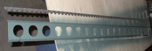 Here is
the LT flap brace and flap hinge, after all the metal prep work and priming
the brace.
Here is
the LT flap brace and flap hinge, after all the metal prep work and priming
the brace. 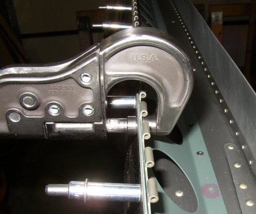
 Here is the
RT flap clecoed into place. I was able to do the RT flap much more
quickly, with less fooling around, than the LT one. I got the flap
brace all prepped and primed. Tomorrow, after the primer has dried
overnight, I will install and rivet the RT flap.
Here is the
RT flap clecoed into place. I was able to do the RT flap much more
quickly, with less fooling around, than the LT one. I got the flap
brace all prepped and primed. Tomorrow, after the primer has dried
overnight, I will install and rivet the RT flap. 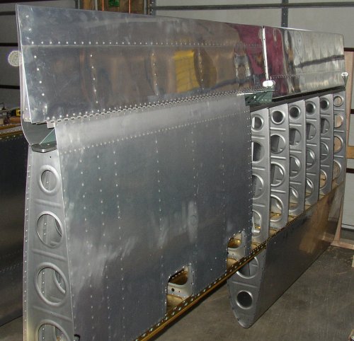 RT flap riveted
into place
RT flap riveted
into place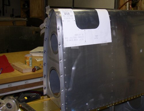 LT
wing landing light template in place. I had it placed once, then I
decided it was about 1/16" off, so I redid its positioning.
LT
wing landing light template in place. I had it placed once, then I
decided it was about 1/16" off, so I redid its positioning.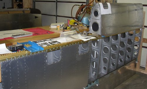 LT
wing landing light ready to make the big cut.
LT
wing landing light ready to make the big cut.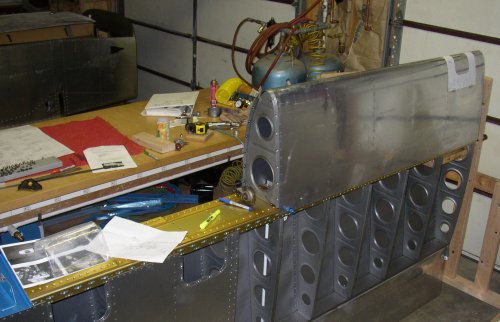 Like
I said, read directions and measure many times before making this huge
cut. I had initially thought the light was supposed to go at the
middle of the wing, next to the fuel tank. After reading the
directions again, I realized they said I should put it out between the last
and next-to-last outboard ribs.
Like
I said, read directions and measure many times before making this huge
cut. I had initially thought the light was supposed to go at the
middle of the wing, next to the fuel tank. After reading the
directions again, I realized they said I should put it out between the last
and next-to-last outboard ribs.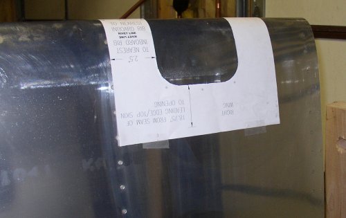 Here's
the template in its proper location
Here's
the template in its proper location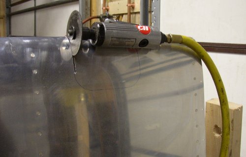 Omigod!!
Here goes the cut. I had to do it and control the cutter very
carefully. This tool cuts through this thin aluminum like a hot knife
through butter. One slip or one grabbing cutter, and I am dead.
I cut it to within about 1/16" - 1/8" of the line, further from
the line in the corners.
Omigod!!
Here goes the cut. I had to do it and control the cutter very
carefully. This tool cuts through this thin aluminum like a hot knife
through butter. One slip or one grabbing cutter, and I am dead.
I cut it to within about 1/16" - 1/8" of the line, further from
the line in the corners.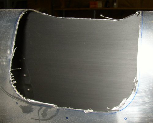 Pretty ragged hole after the first cut.
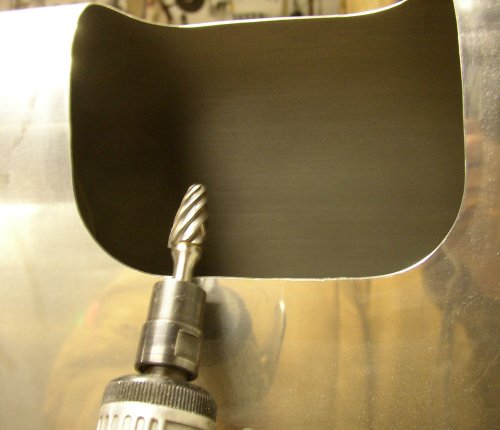 Next I
trimmed it back almost to the line with this very aggressive carbide
aluminum cutter. Again, I had to be very careful to limit the speed of
the cutter, hold it firmly, and cut lightly and gently.
Next I
trimmed it back almost to the line with this very aggressive carbide
aluminum cutter. Again, I had to be very careful to limit the speed of
the cutter, hold it firmly, and cut lightly and gently.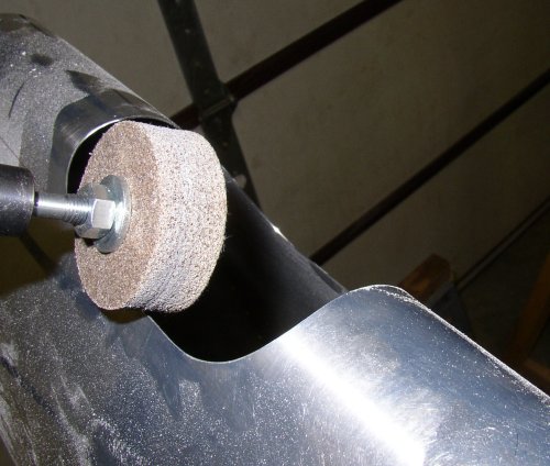 Final trim and smoothing back to the line was done with this Scotchbrite 7A
Medium wheel. There was less chance of this suddenly going way over
the line.
Final trim and smoothing back to the line was done with this Scotchbrite 7A
Medium wheel. There was less chance of this suddenly going way over
the line.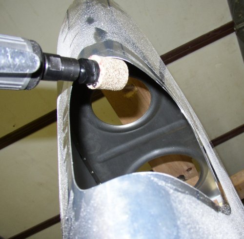 Then
I used this Scotchbrite 5S Fine wheel to polish the edge.
Then
I used this Scotchbrite 5S Fine wheel to polish the edge.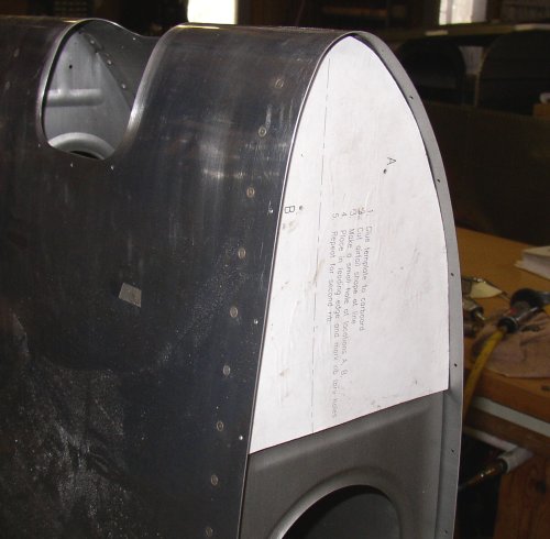 This
is the template for laying out the nutplates for the inboard and outboard
ribs, which hold the light retaining bracket in place. Lots of fun
working in that little space. Supposedly you can put these in when the
wing is complete, but I think it would be about impossible if you didn't at
least have access through the end rib, as I do here.
This
is the template for laying out the nutplates for the inboard and outboard
ribs, which hold the light retaining bracket in place. Lots of fun
working in that little space. Supposedly you can put these in when the
wing is complete, but I think it would be about impossible if you didn't at
least have access through the end rib, as I do here.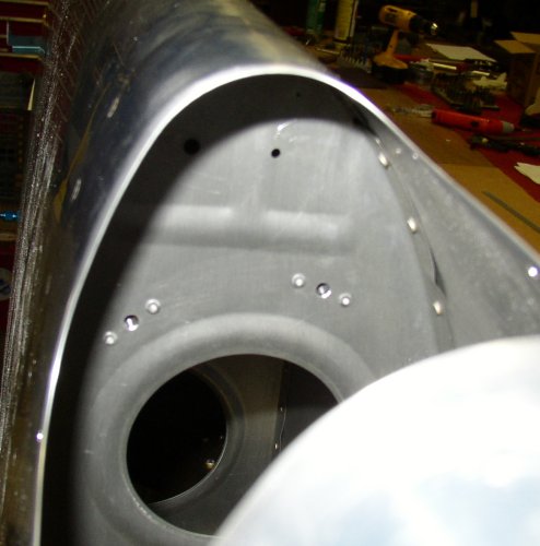 Nutplates are in place on LT wing. Even using pop rivets, this was a rather difficult
and time-consuming process, especially on the inboard rib, shown here,
looking through the cutout for the light lens.
Nutplates are in place on LT wing. Even using pop rivets, this was a rather difficult
and time-consuming process, especially on the inboard rib, shown here,
looking through the cutout for the light lens.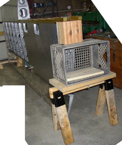 I spent
some time making a new, better RT wing root stand, so I can flip the RT wing
over with the flaps and ailerons installed. I did this so I could
start laying out the RT wing light cutout. I marked the cutout, but
decided to wait until I am more rested to actually make the dangerous cut.
I spent
some time making a new, better RT wing root stand, so I can flip the RT wing
over with the flaps and ailerons installed. I did this so I could
start laying out the RT wing light cutout. I marked the cutout, but
decided to wait until I am more rested to actually make the dangerous cut.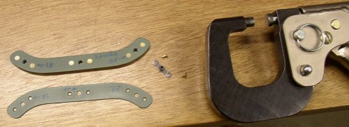 Riveting the nutplates onto the lens retaining strips. I can't do any
more on the LT wing light, because I have ordered the 100 watt round kit
from Duckworks, so I am waiting for that to come to continue with the LT
wing light. So, now I have started in on the RT wing light.
Riveting the nutplates onto the lens retaining strips. I can't do any
more on the LT wing light, because I have ordered the 100 watt round kit
from Duckworks, so I am waiting for that to come to continue with the LT
wing light. So, now I have started in on the RT wing light.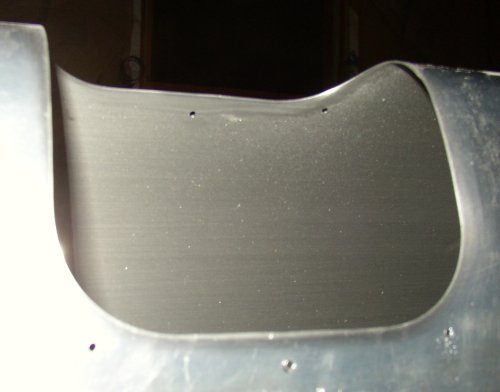 Here's the
RT wing cutout for the landing light.
Here's the
RT wing cutout for the landing light.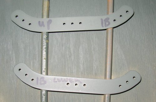 RT wing lens retaining strips all drilled, countersunk, polished, and
primed.
RT wing lens retaining strips all drilled, countersunk, polished, and
primed.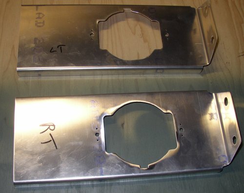 Reflector mounts all deburred and polished.
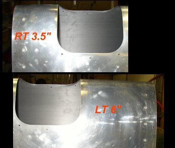 Here are
the 2 wing landing light cutouts superimposed.
Here are
the 2 wing landing light cutouts superimposed. 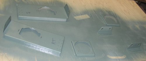 Then
I did all the metal prep and primed the reflector mounts parts.
Then
I did all the metal prep and primed the reflector mounts parts. 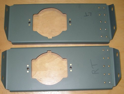 Landing light reflector mounts primed and assembled. I had to mount
each end, then mark where they joined and rivet each of them together with
the ten 470 rivets. The Duckworks kit didn't say much about how to do
this, nor did it include any of the rivets for it, but I just did it with my
own ideas and used rivets from my supply.
Landing light reflector mounts primed and assembled. I had to mount
each end, then mark where they joined and rivet each of them together with
the ten 470 rivets. The Duckworks kit didn't say much about how to do
this, nor did it include any of the rivets for it, but I just did it with my
own ideas and used rivets from my supply.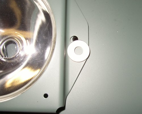 Washers to
hold reflector bezel were too big. They're aluminum, though, so they
were easy to cut one side down with the nibbler.
Washers to
hold reflector bezel were too big. They're aluminum, though, so they
were easy to cut one side down with the nibbler.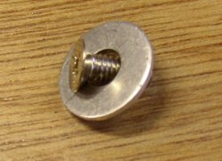 I don't
understand why the Duckworks light kit uses flat washers with flathead
screws, though. I'll email them & see if there's a good
reason. As far as I know, it's an improper hardware match. I
emailed Duckworks about this and a couple other questions, but they did not
respond yet.
I don't
understand why the Duckworks light kit uses flat washers with flathead
screws, though. I'll email them & see if there's a good
reason. As far as I know, it's an improper hardware match. I
emailed Duckworks about this and a couple other questions, but they did not
respond yet.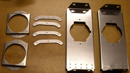 Here are all the reflector mount parts, primed, assembled, then painted
silver for maximum light reflectivity.
Here are all the reflector mount parts, primed, assembled, then painted
silver for maximum light reflectivity.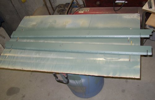 Here
are the two aileron gap seals all drilled, dimpled, polished, and
primed. Good time to quit for the night (0200) and let the paint
harden overnight. Painting in this weather (20 degrees again today) is quite a project.
I have
to warm up the garage, blow hot air from a heat gun onto the parts to get
them warm, shut
down the LP gas heater (don't want flames while I am painting), paint, open
the doors to get rid of the fumes, close the doors, turn the heat back on, and keep
blowing hot air onto the parts to keep them warm while the paint dries.
Here
are the two aileron gap seals all drilled, dimpled, polished, and
primed. Good time to quit for the night (0200) and let the paint
harden overnight. Painting in this weather (20 degrees again today) is quite a project.
I have
to warm up the garage, blow hot air from a heat gun onto the parts to get
them warm, shut
down the LP gas heater (don't want flames while I am painting), paint, open
the doors to get rid of the fumes, close the doors, turn the heat back on, and keep
blowing hot air onto the parts to keep them warm while the paint dries. 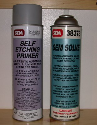 I also use a pretty simple plan for priming. From reading the RV
builders' list, some people really agonize over all sorts of complicated
priming and priming prep procedures. I have a HVLP paint gun, but IMHO
it's way too much trouble to get out the gun & stuff, mix up the paint,
spray a few small parts, then have to clean up the equipment. I just scuff 'em
up with a Scotch-Brite pad, wipe 'em down with SEM Solve degreaser, and spray
'em with
SEM
self-etching primer from a rattle can. Works fine. I was using
the dark green primer color, but I decided to switch over to the light
gray. They also make a black primer, but I like the gray best.
I also use a pretty simple plan for priming. From reading the RV
builders' list, some people really agonize over all sorts of complicated
priming and priming prep procedures. I have a HVLP paint gun, but IMHO
it's way too much trouble to get out the gun & stuff, mix up the paint,
spray a few small parts, then have to clean up the equipment. I just scuff 'em
up with a Scotch-Brite pad, wipe 'em down with SEM Solve degreaser, and spray
'em with
SEM
self-etching primer from a rattle can. Works fine. I was using
the dark green primer color, but I decided to switch over to the light
gray. They also make a black primer, but I like the gray best. When I was riveting
the aileron gap seals on, I was having a hard time of it. When I did
the 426 rivets with the Avery squeezer, they looked good. When I did
them with the pneumatic squeezer, each one was poor; lopsided. I
couldn't understand what I was doing wrong. Eventually, I figured out
that one of the used rivet sets I got from ebay has a bent shaft. Duh!
When I was riveting
the aileron gap seals on, I was having a hard time of it. When I did
the 426 rivets with the Avery squeezer, they looked good. When I did
them with the pneumatic squeezer, each one was poor; lopsided. I
couldn't understand what I was doing wrong. Eventually, I figured out
that one of the used rivet sets I got from ebay has a bent shaft. Duh!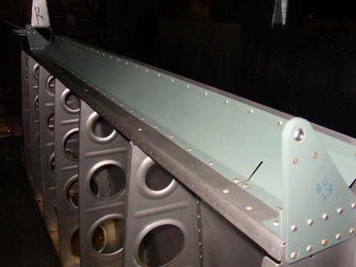 One
of the aileron gap seals installed. BTW, the current RVator says that
Van's just got in a bunch of QB kits where the builders put in some rivets
that should have been left out. You have to drill them out to put the
aileron gaps seals in. They are located along the bottom row of rivets
(in this pic) where the row intersects the ribs. Just drill them out
before putting the gap seal in, and use a longer rivet at that location
(because you're also going through the rib).
One
of the aileron gap seals installed. BTW, the current RVator says that
Van's just got in a bunch of QB kits where the builders put in some rivets
that should have been left out. You have to drill them out to put the
aileron gaps seals in. They are located along the bottom row of rivets
(in this pic) where the row intersects the ribs. Just drill them out
before putting the gap seal in, and use a longer rivet at that location
(because you're also going through the rib).