May 1 - Move the fuselage back
some in the garage, to allow room for the engine and for mounting it.
Put the front of the fuselage up on a higher sawhorse, so I can get the main
gear legs to slide in. Reamed the bolt holes carefully, until the AN5
bolt was a good "hammer in" fit. Installed & torqued the main gear
bolts. Started putting the wheels, tires, and brakes together. I
had to search for quite awhile to find the U810s, but I finally did find
them. The plans are VERY POOR in depicting how the U801, U408s,
Cleveland flange, and U403 all go together. DWG C2, Sect A-A and the
manual, page 10-1, are very sketchy on this. I put it together by
trial and error, about a dozen times, until I had it figured out how they
need to go together. Finally got the LT one assembled.
Disassembled the wheels and prepared to install the tubes and tires.
If you've had your Finish Kit awhile, as I have, be sure you clean out the
inside of the tires thoroughly before putting the tubes in. My tires
had dead moths, leaves, and all sorts of crud in them. Clean
them out well before assembling, to prevent having something in there that
will chafe on your tube. Made my 6 U408s by drilling out 3/8" x 0.083"
tubing, as I couldn't find any of the thinner wall tubing (0.058"?) that the
plans called for. 6.25 hr
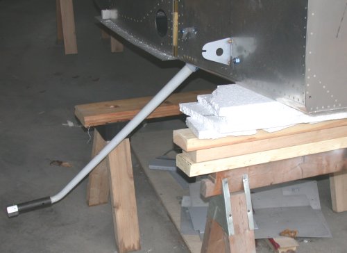
Here is the RT gear leg installed. As you can see from the sawhorses
and the lumber and styrofoam stacked on the higher sawhorse, I had to raise
the fuselage quite a bit to get enough clearance to slide the legs in.
The legs were a very nice, smooth, snug slip fit. I carefully
reamed the bolt hole out a bit at a time, until I had a good "light press
fit", then hammered the bolt home and torqued it.
As I mentioned above, the plans had a very poor depiction how how these
parts go together; both how they are oriented and how they go relative to
each other. Using the sketchy info available in the plans, and by lots
of trial and error, I figured it out. THIS is how they go together.
This is the LT, viewed from the LT fwd outboard, looking aft and inboard.
This is the opposite view of the same LT side parts assembled, looking
forward and outboard from aft and inboard of the LT axle. The nuts
shown are just temporary installation nuts. It took about a dozen
tries to get these parts lined up right. Unless there is a better
drawing somewhere that I did not find, the DWG C2, sect A-A is very
incomplete in showing how these go together.
Here
are the wheels and brakes, as they come out of the box.
Here are the wheels apart, ready to assemble. Take the valve stem core
out of the tube before assembling, and blow it up and let it deflate to a
natural state before trying to put it in the tire.
May 2 - Assemble wheels & tires.
Update web page 1.0 hr + 2.5 hr doc
One of a flock of turkeys crossing the road by my house.
The big
brass nut & silver washer on the tube get screwed down to the tube, and will
sit inside the hole in the center of the wheels. Lube the grommet that
the valve stem will pass through on the outer wheel half, and shove the
outer wheel half down onto the valve stem. Be very careful to
not pinch the tube, and make sure the wheels mate fully and evenly.
Use plenty of baby powder on the tube. The tire sidewalls, and
especially the bead, are VERY stiff, but the tube WILL go in there, after
some work. I also put a film of dish detergent on the bead, to help it
slide out and seat when the tube is inflated. Oh, and take the valve
stem core OUT before putting the tube in, and leave it out for the first 3
or so times you fill up the tube with air. Filling the tube,
then letting the air run out, is important for flexing the tube and helping
it get into a good relaxed position before you put in the valve stem core
and do the final inflation.
Here are the completely assembled wheels, tubes, and tires, ready to go on
the axles. The white is baby powder residue, used in installing the
tube.
May 5 - Disassemble front wheel, clean tape
residue from wheel, polish small rust spot on bearing race and oil it.
The front wheel comes with the bearings taped to the outside of the wheel.
You should get the tape off ASAP, and be sure to clean off the tape residue,
You don't want the tube sticking or chafing on anything. Also,
you should oil the bearings and races as soon as you get your finish kit, to
prevent rust from forming on them before you assemble and mount the wheel.
0.25 hr
May 10 - I've been kinda lax on working on the
plane lately. I cycle through spells of high interest in shooting, and
I've been going through one of those cycles lately. Plus I
didn't shoot all winter because the snow was too deep to walk out to the
target area. So, I've been shooting 6PPC, .50 cal, and others with my
Dad lately.
This is a
new Bluegrass Armory Viper .50 BMG bolt action single shot rifle I just got.
I'm working on the deck here, lapping in the scope rings, before mounting
the Nightforce scope & firing it.
May 11 - Assemble front wheel, tube, & tire,
with Karla's help. The front wheel was harder to squeeze together and
install the bolts than the main wheels were. Also, the front
tube is much thinner and more flexible, so it's much easier to get it caught
between the 2 wheel halves. You have to be very careful that the tube
is not caught between the wheels halves when putting the 3 bolts in. I
squeezed the halves together, and Karla put the nuts on loosely. I
loosened the nuts so they were only holding by a couple threads, then
reached in and used my finger to push the tube out of the space between the
2 halves. Then, I slowly put some air into the tube, to let the tube
pull itself out of the joint between the wheel halves. Make sure you
can hear and feel good metal-to-metal contact as the wheel halves come
together; otherwise you may have a part of the tube stuck in between the
halves. Make sure you resolve any tube interference problems before
tightening the wheel bolt nuts, or you'll hose the tube. Torqued the 3
nuts holding the wheel together, then it was time to head off to NHIS for a
4 day racing weekend. 0.5 hr
May 12 - update web site from NHIS
0.5 hr doc
May 22 - assemble RT U810, U408s, Cleveland
flange, U403. Prep & prime RT U810. 1.0
hr
May 25 - assemble RT brake/wheel assy - adjust
length & squareness of U408s. Decided the U408s I'd made (by drilling
out heavier wall tubing) sucked. The ends were not square, even though
I'd cut them carefully on the bandsaw, and the holes I'd drilled in them
were not centered, because I'd done it with a hand drill. Redid the
U408s properly by chucking up some tubing in the lathe, then cutting each
end perfectly square, plus drilling them out to 1/4" with the lathe.
Reassembled RT brake & wheel assembly. Checked for proper clearance to
U810. 4.5 hr
remaking the U408 spacers on the lathe. This makes a big difference in
making good square ends and precise lengths.
Turkey
feeding in the front yard.
May 26 - Worked on RT axle nut and cotter pin
holes in axle. Making a heavy punch mark really screws up the aluminum
nut threads when you try to back the nut off to drill the holes. FIRST
LESSON LEARNED: when you make the punch mark called for in the manual
(for the axle nut), make it the lightest one you can still see after you
remove the nut for axle cotter pin hole drilling. The deeper your
punch mark is, the more you'll disturb the steel threads and the more
that'll screw up the aluminum nut threads when you try to remove the nut.
Cleaned up axle threads with thread file after drilling the cotter pin
holes, and reassembled wheel & brake assy. SECOND LESSON LEARNED:
Don't tighten the axle nut too much. Even as tight as you can do it
with your hand is too tight. Tighten it with your hand until it just
meets resistance. You can also wiggle the top of the wheel in & out as
you tighten the nut, and stop as soon as the wheel play stops. Either
way gets you too the same spot. My first attempt was a hair too tight,
and the wheel didn't spin quite as freely as it did when backed off a bit as
described. So, I went through the whole punch/remove nut/drill/clean
threads routine again, using 2 different nut holes. THIRD LESSON
LEARNED: You may note that the manual has you putting the tires on
AFTER you get the wheel/brake assy all set and the wheel axle nuts drilled.
This is because the tire bulges out a bit from the wheel, and makes it even
harder to drill your cotter pin holes perpendicular to the axle, if (as I
did) you need to run a cleanup bit through nut & axle so the cotter pin will
go all the way through OK. Safety-wired the brake calipers and
prepped and primed the LT U810. 3.0 hr + 1.0
hr doc
May 27 - assemble LT brake/wheel parts
1.5 hr
HANGAR - I've also begun work on building my
own hangar. I looked into it back in January at Claremont, NH (CNH).
At that time, the airport manager thought funding would be approved for the
city to build at least 6 T-hangars, so I didn't bother proceeding with the
expense and administrative headaches of trying to build my own. I just
found out that the city's lowest bid on the project was over $100K over
budget, so that plan is off at least until next year. So, I've been
very busy with dozens of phone calls, getting all the processes going to
build my own. At least CNH has a better attitude toward pilots &
building hangars than many of the local airports. I don't think any
new hangars have been built in NH for about 30 years. I've been
on a waiting list at CNH for 3 years for one of their rusty old hangars.
About the only way to get into a hangar in NH is for someone to die, crash
their plane, or lose their medical. I will be spending lots of weekday
time working on all the planning for this hangar. One benefit is that
someone else just built the first one at CNH, so I can follow in his
footsteps. He went through a lot of hassles to get it done, but
it should be easier for me following right behind him. I am committed
to doing it, and I hope to have it done by the end of the year.
This is
Dick Love's hangar, just being completed now. Mine will go right
beside it (behind it in this pic), and be the same color. Depending on
what I get back for estimates, it may be the same building, from the same
supplier (Morton), or from a local garage builder. Dick's is 48' wide
and 45' deep, with a 41' door. Mine probably won't be quite as deep,
and maybe not quite as wide. It's actually a wood building, with wood
posts and rafter trusses, even though it looks like a metal building.
See HANGAR page for details.
May 30 - mark & drill LT axle nut, install LT
brake caliper, start layout for nose gear leg. The LT axle nut process
went much smoother than the RT side had. Karla helped slide out the
front sawhorse, and THE RV STANDS ON ITS OWN LEGS! Still
*&^%$ raining - it's been raining for over a week.
3.75 hr
The RV stands on its own two main gear legs! Next, I have to get those
places on the firewall riveted, so I can proceed with hanging the engine.
May 31 - Remove F771 front top fuselage skin,
remove and cut F745R rib. Update web site
1.0 hr doc
cut
off the ends of the F745 ribs, so I can reposition the aft part of them
(that the instrument panel fastens to). I will rivet an angle bracket
onto the piece I cut off, and move it laterally to clear my avionics.
SEE MY JUNE ENGINE PAGE for info & pics on
drilling, reaming, and installing the nose gear leg.
 Here is the RT gear leg installed. As you can see from the sawhorses
and the lumber and styrofoam stacked on the higher sawhorse, I had to raise
the fuselage quite a bit to get enough clearance to slide the legs in.
The legs were a very nice, smooth, snug slip fit. I carefully
reamed the bolt hole out a bit at a time, until I had a good "light press
fit", then hammered the bolt home and torqued it.
Here is the RT gear leg installed. As you can see from the sawhorses
and the lumber and styrofoam stacked on the higher sawhorse, I had to raise
the fuselage quite a bit to get enough clearance to slide the legs in.
The legs were a very nice, smooth, snug slip fit. I carefully
reamed the bolt hole out a bit at a time, until I had a good "light press
fit", then hammered the bolt home and torqued it.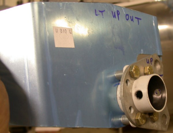 As I mentioned above, the plans had a very poor depiction how how these
parts go together; both how they are oriented and how they go relative to
each other. Using the sketchy info available in the plans, and by lots
of trial and error, I figured it out. THIS is how they go together.
This is the LT, viewed from the LT fwd outboard, looking aft and inboard.
As I mentioned above, the plans had a very poor depiction how how these
parts go together; both how they are oriented and how they go relative to
each other. Using the sketchy info available in the plans, and by lots
of trial and error, I figured it out. THIS is how they go together.
This is the LT, viewed from the LT fwd outboard, looking aft and inboard.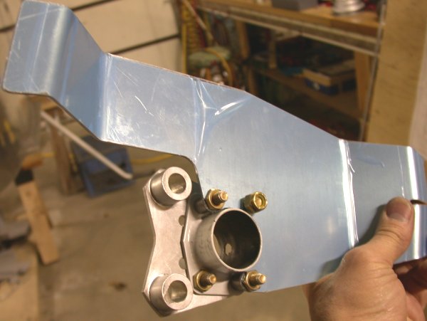 This is the opposite view of the same LT side parts assembled, looking
forward and outboard from aft and inboard of the LT axle. The nuts
shown are just temporary installation nuts. It took about a dozen
tries to get these parts lined up right. Unless there is a better
drawing somewhere that I did not find, the DWG C2, sect A-A is very
incomplete in showing how these go together.
This is the opposite view of the same LT side parts assembled, looking
forward and outboard from aft and inboard of the LT axle. The nuts
shown are just temporary installation nuts. It took about a dozen
tries to get these parts lined up right. Unless there is a better
drawing somewhere that I did not find, the DWG C2, sect A-A is very
incomplete in showing how these go together.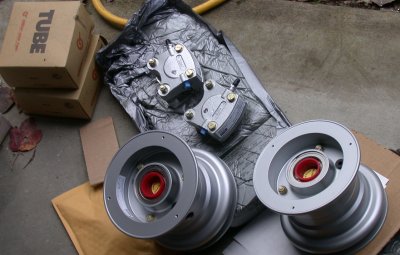 Here
are the wheels and brakes, as they come out of the box.
Here
are the wheels and brakes, as they come out of the box.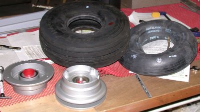 Here are the wheels apart, ready to assemble. Take the valve stem core
out of the tube before assembling, and blow it up and let it deflate to a
natural state before trying to put it in the tire.
Here are the wheels apart, ready to assemble. Take the valve stem core
out of the tube before assembling, and blow it up and let it deflate to a
natural state before trying to put it in the tire.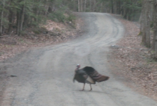 One of a flock of turkeys crossing the road by my house.
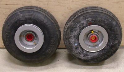 Here are the completely assembled wheels, tubes, and tires, ready to go on
the axles. The white is baby powder residue, used in installing the
tube.
Here are the completely assembled wheels, tubes, and tires, ready to go on
the axles. The white is baby powder residue, used in installing the
tube.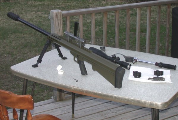 This is a
new Bluegrass Armory Viper .50 BMG bolt action single shot rifle I just got.
I'm working on the deck here, lapping in the scope rings, before mounting
the Nightforce scope & firing it.
This is a
new Bluegrass Armory Viper .50 BMG bolt action single shot rifle I just got.
I'm working on the deck here, lapping in the scope rings, before mounting
the Nightforce scope & firing it.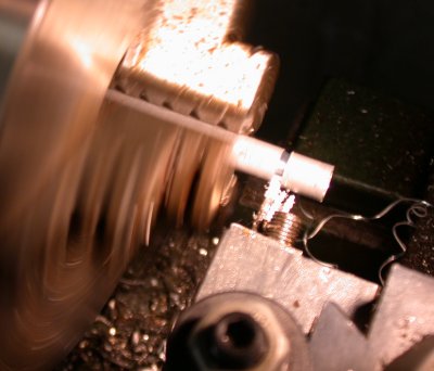 remaking the U408 spacers on the lathe. This makes a big difference in
making good square ends and precise lengths.
remaking the U408 spacers on the lathe. This makes a big difference in
making good square ends and precise lengths.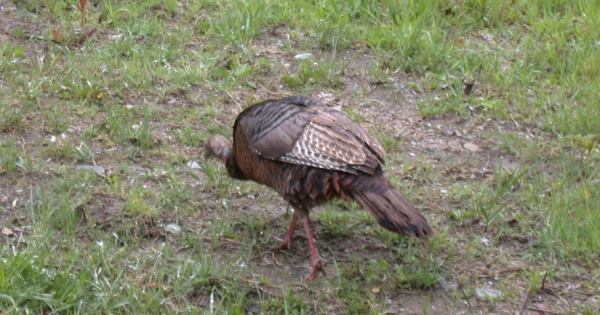 Turkey
feeding in the front yard.
Turkey
feeding in the front yard.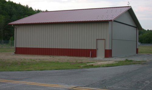 This is
Dick Love's hangar, just being completed now. Mine will go right
beside it (behind it in this pic), and be the same color. Depending on
what I get back for estimates, it may be the same building, from the same
supplier (Morton), or from a local garage builder. Dick's is 48' wide
and 45' deep, with a 41' door. Mine probably won't be quite as deep,
and maybe not quite as wide. It's actually a wood building, with wood
posts and rafter trusses, even though it looks like a metal building.
See
This is
Dick Love's hangar, just being completed now. Mine will go right
beside it (behind it in this pic), and be the same color. Depending on
what I get back for estimates, it may be the same building, from the same
supplier (Morton), or from a local garage builder. Dick's is 48' wide
and 45' deep, with a 41' door. Mine probably won't be quite as deep,
and maybe not quite as wide. It's actually a wood building, with wood
posts and rafter trusses, even though it looks like a metal building.
See 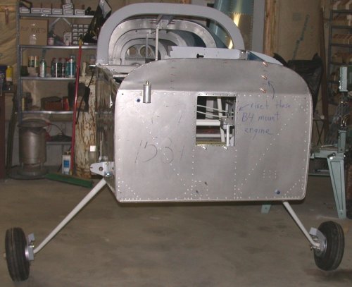 The RV stands on its own two main gear legs! Next, I have to get those
places on the firewall riveted, so I can proceed with hanging the engine.
The RV stands on its own two main gear legs! Next, I have to get those
places on the firewall riveted, so I can proceed with hanging the engine.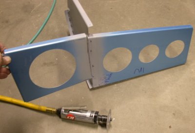 cut
off the ends of the F745 ribs, so I can reposition the aft part of them
(that the instrument panel fastens to). I will rivet an angle bracket
onto the piece I cut off, and move it laterally to clear my avionics.
cut
off the ends of the F745 ribs, so I can reposition the aft part of them
(that the instrument panel fastens to). I will rivet an angle bracket
onto the piece I cut off, and move it laterally to clear my avionics.