Apr 16 - Prime custom rudder
cable tubing. Remake and fit custom lower baggage area panel in .016
aluminum. Rivet baggage frame into place. 3.0
hr
Apr 17 - Finish riveting custom
baggage frame. Riveted the WRONG (old) lower panel in. Removed
wrong panel and primed the correct new one. 1.5
hr
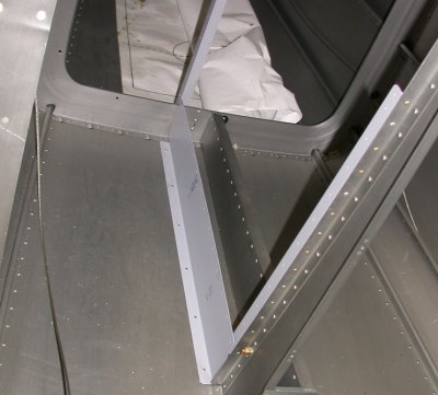
Here
is the custom baggage compartment, with the fwd upright frame (foreground),
aft upright frame (center background), and lower panel all riveted into
place. I had to take out the lower panel and rivet it back in because
I initially grabbed the old (heavier) one by mistake.
Apr 18 - Reinstalled correct
custom baggage compartment lower panel. Installed RT fuel tank attach
bracket. Installed rudder cable tube. Cleaned up bench & put
away tools. Installed rudder cable clamps. Fitted RT rudder
cable fairing (an Avery accessory). Found I had to work around the
problem of interference between the rudder cable fairing rivet holes and the
lower fuselage longeron. 5.0 hr
Karla having
fun bucking those rivets for the lower baggage panel.
Here's
the RT fuel tank bracket bolted into place. Karla helped me with
bucking the rivets that go under the bracket.
I
installed the rudder cable sleeve clamps, then decided to add the Avery
fairing that goes over this.
The
view of the rudder cable sleeve and clamp from inside the fuselage shows how
the rivet holes for the Avery fairing are impossible to dimple or
buck. Only the 2 upper aft holes could be dimpled. The rest had
to be countersunk. Part of the trick here is to get the lower fairing
rivets holes as high as possible. Even then, access to them is hidden
by the lower longeron. The lower holes (see arrow) barely clear the
longeron, then the lip of the longeron prevents access to the holes by a
buck or dimple die.
Apr 19 - Found out there's no
way any solid rivet will work on many of the rudder cable fairing mount
holes. I wonder if the extra work in installing these fairings is
worth it, but I am committed to them now. I also don't have any
3/32" pop rivets, so I ordered some flush ones from Aircraft
Spruce. They had a very poor (and odd) selection (-2 only - how useful
are they?), but I ordered them anyway. the 1/8" reach should be
barely enough. Fitted LT rudder cable fairing. Removed pilot
side brake pedals to change brake cylinder mount point, so the brake pedal
neutral position is more forward. Started welding up existing cylinder
mount holes on brake pedals, but MIG welder developed a problem, so I quit
for now. 3.5 hr + 1.0 doc
This
is the outside view of the RT rudder cable fairing area. Only the 2
upper aft holes could be dimpled. The rest had to be countersunk, and
will require pop rivets.
Be
sure to prime the outside of the fuselage skin under the fairings, before
installing the fairings. This will be the only opportunity to prime
under the fairing.
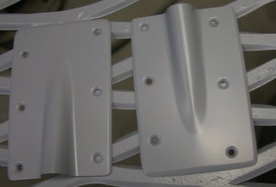
Here are the primed rudder cable fairings.
I decided that the brake pedals were too close to vertical as installed, so
I removed them & took off the primer. I will weld the holes
closed and will drill new holes closer to the edge, as indicated by the dot
above the hole. This will let my foot assume a more natural position
over the brake pedals.
Apr 20 - updating web site after working a small gig
in Franklin, NH 2.0
hr doc
Apr 22 - updating web site from the track at NH Int'l
Speedway 1.5
hr doc
Apr 23 - updating web site from NHIS 1.0
hr doc
Apr 27 - Gosh, I get so busy
every day with "stuff", it's hard to get to the plane.
Finally got back to it after an incredibly dismal weekend at the
track. Welded up the brake cylinder holes in the brake pedals and then
ground them flat. I attempted to pop rivet the rudder cable fairings
into place, but that was a disaster. Finally got them installed
somewhat to my satisfaction, using a mix of 1/8" and 3/32" pop
rivets. I've decided they are definitely not worth the trouble of
installing them, which I suppose is why they don't come in Van's kit.
Wasted a couple hours searching for my builder's notebook, and never did
find it. 4.0 hr + 1.0 doc
Brake pedals holes welded up and ground flat again. Will redrill new
holes and remount them tomorrow.
This is the RT rudder cable fairing. First of all, the holes in the
fuselage were so big, the 3/32" flush pop rivets I'd ordered would not
hold. After having to countersink the holes enough so the fairing
would sit nice and flat, the holes were enlarged bigger than what the pop
rivets could deal with. Then I had to screw around drilling them out
to 1/8", dimpling the fairing for 1/8", countersinking the
fuselage skins more conservatively, and putting in the 1/8" pop
rivets. As you can see, after all my careful work in beveling the
leading edge of the fairing, the fairing does not fit as flush as I had
planned. The heads of the pop rivets were not particularly flush or
smooth, either. I ended up shaving and filing the heads some, so they
were more smooth. This is WAY more trouble than it's worth.
Here's the LT side. Here, I was more prepared after the disasters on
the RT side, and I'd drilled the lower holes higher than I had on the RT
side, so the only countersunk holes were the 2 forward ones. So, I
drilled and countersunk them for 1/8", dimpled the fairing 2 fwd holes
for 1/8", and put it all together. This side fit slightly tighter
than the RT side had. Again, I shaved the heads a bit, using a rivet
shaver and a small hand file. The 4 aft 3/32" pop rivets left the
center shank sticking up a bit from the head, so that had to be cleaned up
so the rivets were as flush as possible. What a pain! I would
not recommend using these fairings! Plus, if I ever have to remove the
cable or the cable clamp, all these rivets will have to be drilled out to
access the clamp screw, further enlarging and aggravating the rivet holes.
JULY, 2004 update - I saw a plane at OSH 04 that had this done
RIGHT. It never occurred to me that this fairing should go on the
INside. Sure looks a hell of a lot better than what I did. Oh
well.....
Apr 28 - I've wasted about 6+
hours over the last 2 days searching for my Builder's Log. I had it in
my hand one minute, and it simply vanished the next. I finally gave up
on it and started a new one. I suppose the old one will turn up
eventually somewhere. I got back to work on the plane; I drilled the
new holes in the pilot's brake pedals, primed them, and reinstalled
them. I like the new installed angle better; I think it will better fit a more
natural foot position, rather than having to pull the front of my foot all
the way back to be parallel with the pedal. 1.25
hr + 6 hr log search
Here
is one of the pedals, with the hole for the brake cylinder moved as close as
possible to the edge of the metal (edge of hole is 1 diameter from the
edge).
Apr 29 - Trying to decide what to
work on next. Decided to remove flap motor and drill it for safety
wire; something I'd skipped before, as I'd been debating safetying it
different from what was specified by Van's. Removed flap motor,
drilled for safety wire, safety-wired flap motor shaft, & reinstalled
flap motor. Fabricated custom baggage compartment fwd panel (F751), so
it only covers the LT side. I will switch between the stock F751
provided with the kit, and will use the custom version when I am using the
custom extended baggage compartment. I needed a F-6114B wear block for
the custom F751. Rather than order one from Van's, I made one from a
piece of Delrin I had laying around. I later found out that my seat
belt anchor kit had them, anyway, even though the stock one was already
installed on the stock F751. I finished making the custom F751 and
primed it. I also clecoed the instrument panel and sub-panel into
place. Then, on a roll, I started in on the cabin frame. Worked
to 0230 fabricating the F631E plates, F631C angles, F631D angles, F732B and
D angles, and the F732E and F732C. 3 pairs of the angles were complex
trapezoid shapes that took a lot of time to get right. The bandsaw was
crucial to making them well. It was enjoyable to get back into some
real fabrication. I'll caption these pics as soon as I get a
chance. Documenting the building here on the web site takes HUGE
amounts of time I could be working on the plane. 12.25 hr
Here is the electric flap motor shaft and rod end, safetied as per Van's
plans. I had thought it would be easier and more effective to just
drill right through the side of the shaft and through the rod end threads,
and put a cotter pin through both pieces. I asked Van's about it, and
they said no one had tried it, and the flap motor was an expensive part to
be experimenting with. I'm sure it would have worked, but it would
have meant I could never adjust the rod end, so I opted for the tried and
true method.
Here is the flap motor shaft, safetied as per Van's plans. I used
heavy 0.041" safety wire for this.
Here is the replacement F-751 baggage panel I ordered. The QB kit came
with one fully completed, but I needed a second optional one, modified for
use when I need to access the custom baggage area, on the left in this pic.
Here is the
finished custom F-751 baggage bulkhead panel. It is trimmed to allow
access into the custom baggage area. You can see in the custom baggage
area the tubing protecting the rudder cable on the LT, and the lower part of
the frame and the lower custom panel on the RT. The main inboard panel
and aft panel are not installed in this pic. I am waiting to install
my autopilot elevator servo (behind this custom F-751 panel) before I rivet
then custom baggage panels into place. This is jut to ensure I have
all the access to the servo I need to get it installed. I will be
ordering the servos from BMA soon.
This is the top of the custom F-751, with the nutplates installed and the F-6114B wear block
installed. I made the wear block from a scrap of Delrin I had laying
around. Later, I found out that, even though the QB kit came with the
F-751 already built, the bag of seat belt anchor hardware had the wear
blocks in it, anyway.
I clecoed together all the parts for the instrument panel and sub-panel.
1 These
are all the pieces I fabricated for the F-631 cabin frame assembly.
The F-631C, F-631D, and F-732C all involved a lot of cutting to form the
angles shown here. The F-732D had to be squeezed down to 88
degrees. 2 degrees down is not much, so the first time I did it, I did
it to about 20 degrees, and had to scrap it. Even this one is more
than 2 degrees, but it's pretty close. The F-732B angle had to be
opened up to 101 degrees, so that was harder. I laid it as shown onto
a steel table and pounded the vertex with a lead hammer, until I got it
opened up the right amount. Of course, you can't really change the
angle at the vertex, because that's the strongest part of the piece, so what
you are really doing is bowing the legs. A subsequent pic shows what I
mean in more detail.
Jan 26, 2005 update - I don't follow every email on the RV7 Yahoo list (too many
"which rivet gun should I get" and "how should I prime" questions), but I
occasionally look there to see what's going on. Roberta Hegy (who got
her plane flying awhile ago) reported a new Service
Bulletin from Van's for R-7 and R9 people with tipup canopies.
HERE is a link to
the SB. I'm sure glad I happened to catch that message!
Apparently, it's a revision and strengthening of how the aft end of the
F632A channel attaches to the F706A bulkhead.
Apr 30 - Fabricated F-632A
channel. I screwed up one end of it, by drilling holes in it that
should have gone at the other end. But I cleaned it up and saved
it. Fabricated F-631B and F-631B-L. Tried to figure out how all
these parts from DWG 39 are going to go together. Realized all the
F-631A parts have the same part number on them, but they are not all the
same; there are lefts and rights. Drilled out access hole on aft
F-631As. Called Van's about problem locating access hole on aft F-631A
pieces. Bruce said it's OK to just use the fixture locating
hole. I also screwed up one of the F-631A pieces, making the access
hole at the wrong end, thus realizing they are not symetrical, but I have 6
of them and only seem to need 4 for now. So, if I need to use that 6th
one, I'll just make a longer tie plate over the hole. After that, I
was ready to do the aft F-631A layout. I set up a separate table to do
it, but could not proceed, because the manual said the width specified in
the plans for the F-631 assy was a nominal dimension, and I'd need to
measure the actual fuselage width. I spent a huge amount of time
studying Drawings 18, 20, 25, and 40, trying to figure out exactly where the
F-631C angles were supposed to go. The fuselage changes width fwd and
aft, so I had to determine exactly where it was to be located, in order to
get an accurate width measurement. I also needed to measure from the
INside of the 2 F-631C brackets, so I also had to get them located properly,
in order to measure the width. I started by deciding that I'd need to
drill out the pop rivets holding the F-721B, F-705F, and F-718 together in
the Quick Build kit. 8.0 hr
Here is the F-632A channel. One end has 4 holes, and the other end
gets cut at an angle. These 2 things happen at different distances
from the end. I marked both ends, then proceeded to drill the holes in
the end that should have been the cut line.
I initially drilled the 4 holes in the wrong end - the end that was cut in
at an angle from the end. So, I ended up with 4 half holes in the
middle of my cut line. I smoothed and polished it out as shown
here, so it won't develop any cracks.
Here is the detail on the F-732B. The angle had to be opened up to 101
degrees. As I said earlier, I did that by laying the angle on a steel
plate, then pounding the vertex with a lead hammer. You can't really
bend the vertex, because that's the strongest part of the angle. So
what I ended up with is the 2 legs bowed out to 101 degrees. In order
to eliminate, or at least reduce, the bowing, I then filed the outside of
the legs flat, concentrating the filing at the vertex, as that's where
there's the most metal. So, you can see from the filing marks how it
worked on this piece. I think it needs a bit more filing. The
filing sharpens the vertex, so I polished that round when I was done filing.
This shows where the access hole should be centered on the 2 aft F-631A
channels. That point comes at exactly the 10:00 position on the very
edge of the tooling fixture hole, so there's no way you're going to start
any new pilot hole there. Dan
Checkoway's site mentioned the exact same thing. Like me, he
called Van's about it, and they said the position isn't critical, as long as
the hole doesn't get too near any edge. So, I just used the existing
hole as my hole cutter pilot drill point. You'd think that, if
everyone is calling Van's about this discrepancy, they'd either move the
tooling hole or update the plans.
 Here
is the custom baggage compartment, with the fwd upright frame (foreground),
aft upright frame (center background), and lower panel all riveted into
place. I had to take out the lower panel and rivet it back in because
I initially grabbed the old (heavier) one by mistake.
Here
is the custom baggage compartment, with the fwd upright frame (foreground),
aft upright frame (center background), and lower panel all riveted into
place. I had to take out the lower panel and rivet it back in because
I initially grabbed the old (heavier) one by mistake.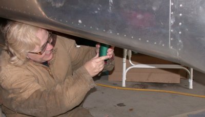 Karla having
fun bucking those rivets for the lower baggage panel.
Karla having
fun bucking those rivets for the lower baggage panel.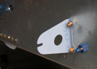 Here's
the RT fuel tank bracket bolted into place. Karla helped me with
bucking the rivets that go under the bracket.
Here's
the RT fuel tank bracket bolted into place. Karla helped me with
bucking the rivets that go under the bracket.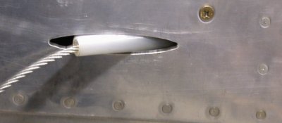 I
installed the rudder cable sleeve clamps, then decided to add the Avery
fairing that goes over this.
I
installed the rudder cable sleeve clamps, then decided to add the Avery
fairing that goes over this.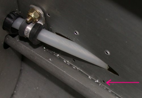 The
view of the rudder cable sleeve and clamp from inside the fuselage shows how
the rivet holes for the Avery fairing are impossible to dimple or
buck. Only the 2 upper aft holes could be dimpled. The rest had
to be countersunk. Part of the trick here is to get the lower fairing
rivets holes as high as possible. Even then, access to them is hidden
by the lower longeron. The lower holes (see arrow) barely clear the
longeron, then the lip of the longeron prevents access to the holes by a
buck or dimple die.
The
view of the rudder cable sleeve and clamp from inside the fuselage shows how
the rivet holes for the Avery fairing are impossible to dimple or
buck. Only the 2 upper aft holes could be dimpled. The rest had
to be countersunk. Part of the trick here is to get the lower fairing
rivets holes as high as possible. Even then, access to them is hidden
by the lower longeron. The lower holes (see arrow) barely clear the
longeron, then the lip of the longeron prevents access to the holes by a
buck or dimple die. 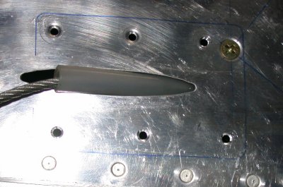 This
is the outside view of the RT rudder cable fairing area. Only the 2
upper aft holes could be dimpled. The rest had to be countersunk, and
will require pop rivets.
This
is the outside view of the RT rudder cable fairing area. Only the 2
upper aft holes could be dimpled. The rest had to be countersunk, and
will require pop rivets.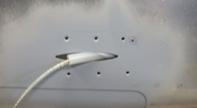 Be
sure to prime the outside of the fuselage skin under the fairings, before
installing the fairings. This will be the only opportunity to prime
under the fairing.
Be
sure to prime the outside of the fuselage skin under the fairings, before
installing the fairings. This will be the only opportunity to prime
under the fairing.
 Here are the primed rudder cable fairings.
 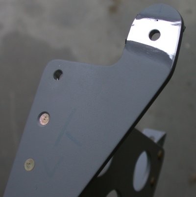 I decided that the brake pedals were too close to vertical as installed, so
I removed them & took off the primer. I will weld the holes
closed and will drill new holes closer to the edge, as indicated by the dot
above the hole. This will let my foot assume a more natural position
over the brake pedals.
I decided that the brake pedals were too close to vertical as installed, so
I removed them & took off the primer. I will weld the holes
closed and will drill new holes closer to the edge, as indicated by the dot
above the hole. This will let my foot assume a more natural position
over the brake pedals. 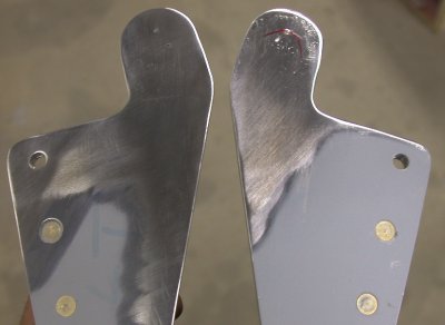 Brake pedals holes welded up and ground flat again. Will redrill new
holes and remount them tomorrow.
Brake pedals holes welded up and ground flat again. Will redrill new
holes and remount them tomorrow.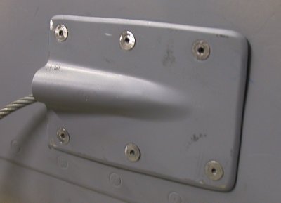 This is the RT rudder cable fairing. First of all, the holes in the
fuselage were so big, the 3/32" flush pop rivets I'd ordered would not
hold. After having to countersink the holes enough so the fairing
would sit nice and flat, the holes were enlarged bigger than what the pop
rivets could deal with. Then I had to screw around drilling them out
to 1/8", dimpling the fairing for 1/8", countersinking the
fuselage skins more conservatively, and putting in the 1/8" pop
rivets. As you can see, after all my careful work in beveling the
leading edge of the fairing, the fairing does not fit as flush as I had
planned. The heads of the pop rivets were not particularly flush or
smooth, either. I ended up shaving and filing the heads some, so they
were more smooth. This is WAY more trouble than it's worth.
This is the RT rudder cable fairing. First of all, the holes in the
fuselage were so big, the 3/32" flush pop rivets I'd ordered would not
hold. After having to countersink the holes enough so the fairing
would sit nice and flat, the holes were enlarged bigger than what the pop
rivets could deal with. Then I had to screw around drilling them out
to 1/8", dimpling the fairing for 1/8", countersinking the
fuselage skins more conservatively, and putting in the 1/8" pop
rivets. As you can see, after all my careful work in beveling the
leading edge of the fairing, the fairing does not fit as flush as I had
planned. The heads of the pop rivets were not particularly flush or
smooth, either. I ended up shaving and filing the heads some, so they
were more smooth. This is WAY more trouble than it's worth.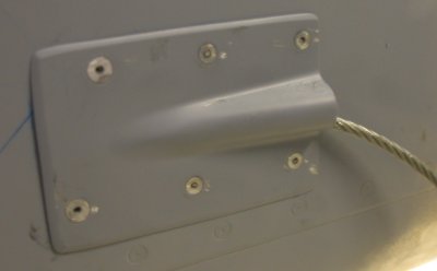 Here's the LT side. Here, I was more prepared after the disasters on
the RT side, and I'd drilled the lower holes higher than I had on the RT
side, so the only countersunk holes were the 2 forward ones. So, I
drilled and countersunk them for 1/8", dimpled the fairing 2 fwd holes
for 1/8", and put it all together. This side fit slightly tighter
than the RT side had. Again, I shaved the heads a bit, using a rivet
shaver and a small hand file. The 4 aft 3/32" pop rivets left the
center shank sticking up a bit from the head, so that had to be cleaned up
so the rivets were as flush as possible. What a pain! I would
not recommend using these fairings! Plus, if I ever have to remove the
cable or the cable clamp, all these rivets will have to be drilled out to
access the clamp screw, further enlarging and aggravating the rivet holes.
Here's the LT side. Here, I was more prepared after the disasters on
the RT side, and I'd drilled the lower holes higher than I had on the RT
side, so the only countersunk holes were the 2 forward ones. So, I
drilled and countersunk them for 1/8", dimpled the fairing 2 fwd holes
for 1/8", and put it all together. This side fit slightly tighter
than the RT side had. Again, I shaved the heads a bit, using a rivet
shaver and a small hand file. The 4 aft 3/32" pop rivets left the
center shank sticking up a bit from the head, so that had to be cleaned up
so the rivets were as flush as possible. What a pain! I would
not recommend using these fairings! Plus, if I ever have to remove the
cable or the cable clamp, all these rivets will have to be drilled out to
access the clamp screw, further enlarging and aggravating the rivet holes.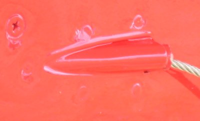 JULY, 2004 update - I saw a plane at OSH 04 that had this done
RIGHT. It never occurred to me that this fairing should go on the
INside. Sure looks a hell of a lot better than what I did. Oh
well.....
JULY, 2004 update - I saw a plane at OSH 04 that had this done
RIGHT. It never occurred to me that this fairing should go on the
INside. Sure looks a hell of a lot better than what I did. Oh
well.....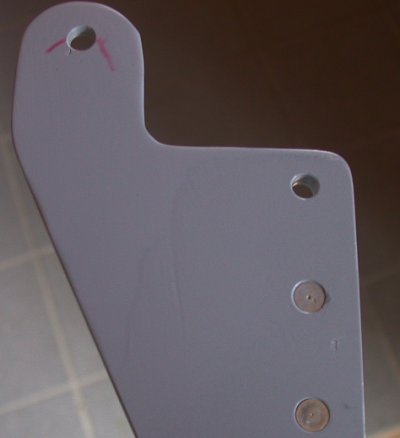 Here
is one of the pedals, with the hole for the brake cylinder moved as close as
possible to the edge of the metal (edge of hole is 1 diameter from the
edge).
Here
is one of the pedals, with the hole for the brake cylinder moved as close as
possible to the edge of the metal (edge of hole is 1 diameter from the
edge).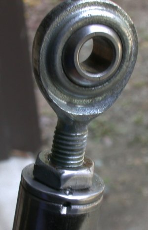 Here is the electric flap motor shaft and rod end, safetied as per Van's
plans. I had thought it would be easier and more effective to just
drill right through the side of the shaft and through the rod end threads,
and put a cotter pin through both pieces. I asked Van's about it, and
they said no one had tried it, and the flap motor was an expensive part to
be experimenting with. I'm sure it would have worked, but it would
have meant I could never adjust the rod end, so I opted for the tried and
true method.
Here is the electric flap motor shaft and rod end, safetied as per Van's
plans. I had thought it would be easier and more effective to just
drill right through the side of the shaft and through the rod end threads,
and put a cotter pin through both pieces. I asked Van's about it, and
they said no one had tried it, and the flap motor was an expensive part to
be experimenting with. I'm sure it would have worked, but it would
have meant I could never adjust the rod end, so I opted for the tried and
true method. 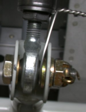 Here is the flap motor shaft, safetied as per Van's plans. I used
heavy 0.041" safety wire for this.
Here is the flap motor shaft, safetied as per Van's plans. I used
heavy 0.041" safety wire for this. 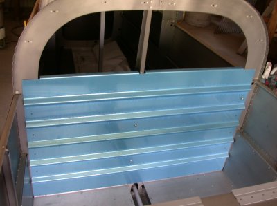 Here is the replacement F-751 baggage panel I ordered. The QB kit came
with one fully completed, but I needed a second optional one, modified for
use when I need to access the custom baggage area, on the left in this pic.
Here is the replacement F-751 baggage panel I ordered. The QB kit came
with one fully completed, but I needed a second optional one, modified for
use when I need to access the custom baggage area, on the left in this pic. 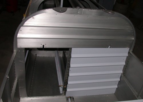 Here is the
finished custom F-751 baggage bulkhead panel. It is trimmed to allow
access into the custom baggage area. You can see in the custom baggage
area the tubing protecting the rudder cable on the LT, and the lower part of
the frame and the lower custom panel on the RT. The main inboard panel
and aft panel are not installed in this pic. I am waiting to install
my autopilot elevator servo (behind this custom F-751 panel) before I rivet
then custom baggage panels into place. This is jut to ensure I have
all the access to the servo I need to get it installed. I will be
ordering the servos from BMA soon.
Here is the
finished custom F-751 baggage bulkhead panel. It is trimmed to allow
access into the custom baggage area. You can see in the custom baggage
area the tubing protecting the rudder cable on the LT, and the lower part of
the frame and the lower custom panel on the RT. The main inboard panel
and aft panel are not installed in this pic. I am waiting to install
my autopilot elevator servo (behind this custom F-751 panel) before I rivet
then custom baggage panels into place. This is jut to ensure I have
all the access to the servo I need to get it installed. I will be
ordering the servos from BMA soon. 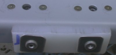 This is the top of the custom F-751, with the nutplates installed and the F-6114B wear block
installed. I made the wear block from a scrap of Delrin I had laying
around. Later, I found out that, even though the QB kit came with the
F-751 already built, the bag of seat belt anchor hardware had the wear
blocks in it, anyway.
This is the top of the custom F-751, with the nutplates installed and the F-6114B wear block
installed. I made the wear block from a scrap of Delrin I had laying
around. Later, I found out that, even though the QB kit came with the
F-751 already built, the bag of seat belt anchor hardware had the wear
blocks in it, anyway. 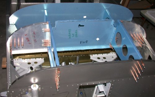 I clecoed together all the parts for the instrument panel and sub-panel.
 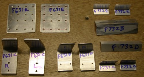 These
are all the pieces I fabricated for the F-631 cabin frame assembly.
The F-631C, F-631D, and F-732C all involved a lot of cutting to form the
angles shown here. The F-732D had to be squeezed down to 88
degrees. 2 degrees down is not much, so the first time I did it, I did
it to about 20 degrees, and had to scrap it. Even this one is more
than 2 degrees, but it's pretty close. The F-732B angle had to be
opened up to 101 degrees, so that was harder. I laid it as shown onto
a steel table and pounded the vertex with a lead hammer, until I got it
opened up the right amount. Of course, you can't really change the
angle at the vertex, because that's the strongest part of the piece, so what
you are really doing is bowing the legs. A subsequent pic shows what I
mean in more detail.
These
are all the pieces I fabricated for the F-631 cabin frame assembly.
The F-631C, F-631D, and F-732C all involved a lot of cutting to form the
angles shown here. The F-732D had to be squeezed down to 88
degrees. 2 degrees down is not much, so the first time I did it, I did
it to about 20 degrees, and had to scrap it. Even this one is more
than 2 degrees, but it's pretty close. The F-732B angle had to be
opened up to 101 degrees, so that was harder. I laid it as shown onto
a steel table and pounded the vertex with a lead hammer, until I got it
opened up the right amount. Of course, you can't really change the
angle at the vertex, because that's the strongest part of the piece, so what
you are really doing is bowing the legs. A subsequent pic shows what I
mean in more detail.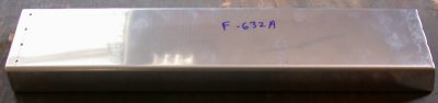 Here is the F-632A channel. One end has 4 holes, and the other end
gets cut at an angle. These 2 things happen at different distances
from the end. I marked both ends, then proceeded to drill the holes in
the end that should have been the cut line.
Here is the F-632A channel. One end has 4 holes, and the other end
gets cut at an angle. These 2 things happen at different distances
from the end. I marked both ends, then proceeded to drill the holes in
the end that should have been the cut line. 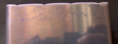 I initially drilled the 4 holes in the wrong end - the end that was cut in
at an angle from the end. So, I ended up with 4 half holes in the
middle of my cut line. I smoothed and polished it out as shown
here, so it won't develop any cracks.
I initially drilled the 4 holes in the wrong end - the end that was cut in
at an angle from the end. So, I ended up with 4 half holes in the
middle of my cut line. I smoothed and polished it out as shown
here, so it won't develop any cracks. 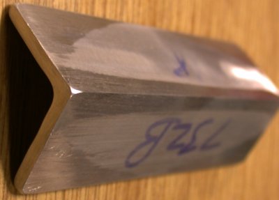 Here is the detail on the F-732B. The angle had to be opened up to 101
degrees. As I said earlier, I did that by laying the angle on a steel
plate, then pounding the vertex with a lead hammer. You can't really
bend the vertex, because that's the strongest part of the angle. So
what I ended up with is the 2 legs bowed out to 101 degrees. In order
to eliminate, or at least reduce, the bowing, I then filed the outside of
the legs flat, concentrating the filing at the vertex, as that's where
there's the most metal. So, you can see from the filing marks how it
worked on this piece. I think it needs a bit more filing. The
filing sharpens the vertex, so I polished that round when I was done filing.
Here is the detail on the F-732B. The angle had to be opened up to 101
degrees. As I said earlier, I did that by laying the angle on a steel
plate, then pounding the vertex with a lead hammer. You can't really
bend the vertex, because that's the strongest part of the angle. So
what I ended up with is the 2 legs bowed out to 101 degrees. In order
to eliminate, or at least reduce, the bowing, I then filed the outside of
the legs flat, concentrating the filing at the vertex, as that's where
there's the most metal. So, you can see from the filing marks how it
worked on this piece. I think it needs a bit more filing. The
filing sharpens the vertex, so I polished that round when I was done filing. 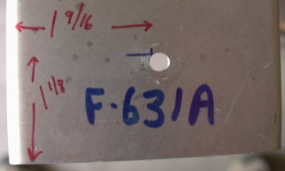 This shows where the access hole should be centered on the 2 aft F-631A
channels. That point comes at exactly the 10:00 position on the very
edge of the tooling fixture hole, so there's no way you're going to start
any new pilot hole there.
This shows where the access hole should be centered on the 2 aft F-631A
channels. That point comes at exactly the 10:00 position on the very
edge of the tooling fixture hole, so there's no way you're going to start
any new pilot hole there.