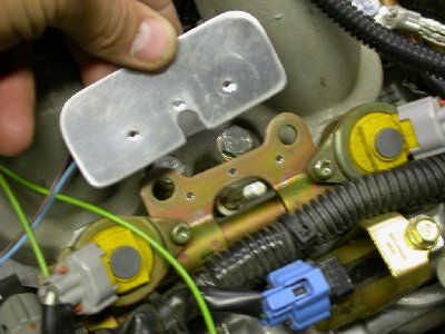
 This is the LT fuel injector plate, with the hold-down rod removed, and the
plate and current limiter base mount bracket drilled for flush rivets.
This is the LT fuel injector plate, with the hold-down rod removed, and the
plate and current limiter base mount bracket drilled for flush rivets.ENGINE WORK October, 2006
A lot of what I am doing right now is wiring related toward getting the engine ready to start. If it's strictly engine wiring, it on this page. If it's more general supporting wiring, it's on the avionics/electric page, so be sure to check there for details
Oct 2 - post question (for the third time!) to STi list about what is that second sensor on my LT header. Install, mark, remove intercooler in prep for relocating oil cooler to under the intercooler. People on the list are saying now that the oil cooler should be moved to under the intercooler. I can see already that mounting the cooler on the firewall is going to be a real bitch with that firewall recess right there in the way. Once again, the advice I got way back to go with the recess was a VERY bad idea. If you are putting an Eggenfellner engine in, be sure you replace the firewall recess with the flat panel, available from Van's. 0.5 hr
Oct 3 - finally get answer from Jan about second sensor on LT header - it's EGT. Drain oil cooler and oil lines, and remove oil cooler and brackets. Realized there is NO WAY this oil cooler is going to go under the intercooler; it's at least 2" too wide to fit. The IC only clears the SC pulley by 3/16" or less, and it's 6" wide. The oil cooler is 8" wide and 10-11" long depending on what's being measured. 1.25 hr
Oct 4 - finish draining oil cooler and oil lines. Look up replacement oil coolers online and in ACS catalog. Wrap cold-shrink tape on engine harness near ECM 1.0 hr
Oct 5 - Sent several emails to STi list, including asking Robert Paisley what his results were with the cooler in the front. Robert replied and said there's no problem with the cooler where it is in the front. I don't know where the momentum to move the oil cooler started, but I am done with that tangent. Good! One less thing to have to deal with. Ordered oil thermostat from Racer Parts Wholesale. Received B&C order of current limiter, engine ground strap, and a couple other items. Installed engine ground strap. Trying to find a place to mount the current limiter. It's very difficult to find a suitable location near the alternator. The current limiter base is large and has VERY long studs on it. I could tie-wrap it to one of the intake manifold runners, but that would be a pretty hokey installation. Finally figured out I can mount it to part of the clamp and bracket that hold the LT side fuel injectors in place. Fabricated a bracket to attach to the fuel injector mount bracket, so the current limiter base can mount to that. I made it 3 times before I was satisfied with it. Finish & prime bracket. Mill fuel injector hold-down rod to compensate for thickness of the current limiter bracket. Cut down long studs on current limiter base. Rivet current limiter base bracket onto LT fuel injectors hold-down bracket. Torque LT fuel injectors hold-down stud nut to 15 inch pounds. Install current limiter base and limiter. 3.25 hours
This is the LT fuel injector plate, with the hold-down rod removed, and the
plate and current limiter base mount bracket drilled for flush rivets.
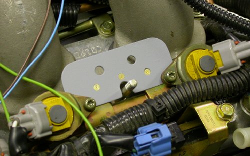 And here it is with the primed mount bracket riveted on. This gives me
a nice flat surface to bolt the current limiter base to. The LT side
fuel injectors are on either side of the bracket, at each intake port.
And here it is with the primed mount bracket riveted on. This gives me
a nice flat surface to bolt the current limiter base to. The LT side
fuel injectors are on either side of the bracket, at each intake port.
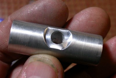 I milled 0.070" off the top of the fuel injector hold-down rod, to make up for the
thickness of the current limiter base mount bracket, so I'd end up with the
same thread engagement I started with.
I milled 0.070" off the top of the fuel injector hold-down rod, to make up for the
thickness of the current limiter base mount bracket, so I'd end up with the
same thread engagement I started with.
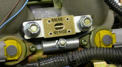 Here is the mounted current limiter. Nice, clean installation.
Now, I need to wire the alternator B lead through the limiter.
Here is the mounted current limiter. Nice, clean installation.
Now, I need to wire the alternator B lead through the limiter.
Oct 6 - called MT to check on status of my MT prop controller upgrade. I got on their list nearly a year ago. Douglas Turner to call back. Removed alternator Battery wire from its protective harness, and rewired it through the current limiter. Installed alternator belt and supercharger pulley. NOTE: the belt goes on the fwd set of alternator pulley grooves. Torque SC pulley bolt to 133 ft lb. Tighten up all alternator bolts. The alternator barely fits as presently installed (pushed as far as it will go toward the SC drive pulley), but not worth the trouble to remove it and grind a bit more from the top of the engine block. NOTE: if & when the alternator is removed later, I should grind the clearance a bit more than it presently is. NOTE: alternator belt is Dayco 5040270. Spent some time pondering how to best run the coolant level warning wires. Update web site. 4.25 hr + 1.0 hr doc
Oct 8 - looking at low coolant level warning wiring & how to route it. Looking at all the wires that have to tie to the switched side of the main contactor. Considering adding a power distribution block to tie all the switched main leads. Looking at my removable tray that currently has the BMA A/P controller mounted on it, and considering moving the BMA A/P controller back to the batteries area. The problem is that the "removable" tray, which the BMA controller is presently mounted to, is getting harder and harder to remove as I add more and more components and wires to that area. I finally decided to go with what I already have, in terms of the power distribution block. I can use the hot side of the 3 main bus fuse blocks to distribute the power. Didn't really accomplish anything - just lots of pondering. 2.5 hr
Oct 9 - trim edges of removable tray so it goes in and out easier. Secure switched side of main contactor and start placing alternator "B" lead. Update web site 0.5 hr + 0.5 hr doc
Oct 10 - called MT again to check on controller upgrade status. Received oil cooler thermostat from Racer Parts Wholesale. Removed and boxed Andair fuel selector valve. Boxed up MT prop controller. Looked up old emails and found Jan's email about the source of the steel-braided oil hoses, as well as Robert's emails about which oil hose connection is IN and which is OUT. OUT is the FWD connection at the oil filter. 1.5 hr
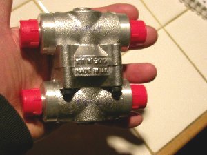 I got the oil cooler thermostat today. Now, I will need to get some
different oil cooler lines made up, so I can plumb this into the system.
I got the oil cooler thermostat today. Now, I will need to get some
different oil cooler lines made up, so I can plumb this into the system.
Oct 11 - Another STi customer tells me Jan had the oil coolers made up with a restrictive orifice. By doing the cooling control properly with a thermostat, the orifice is counter-productive. Emailed Jan as to how I can get this orifice removed. Jan says there is none. Good - one less thing to have to deal with! Mailed MT prop controller back to MT for upgrade. Mailed fuel selector valve to Andair in UK for upgrading to 12" extension, to go with the console I am going to make and install. Andair's responsiveness in getting me the fuel valve extension for the console kit has been very good this time. The Andair shipment alone cost $35! Reinstall oil cooler. Try to find a place to mount the thermostat; harder than expected; issues with proximity to header, frame rails, and avoiding sharp angles. Finally decided to place it inline with the existing hoses, then work out the mounting, rather than vice-versa. Measure lengths of hoses needed. 1.5 hr
Final DIRTY DEAL on the sleazy, crooked hangar situation at Claremont Municipal Airport.
Oct 12 - mailed oil cooler hoses to Southeastern Hose to get the 2 hoses made into 4, so I can plumb in the oil thermostat.
Oct 14 - route and secure MAP vacuum line to near firewall, awaiting further routing. 1.0 hr
Oct 15 - Figured out I can make a firewall bulkhead fitting to pass the vacuum line through the firewall, rather than all the drilling and holes for one of those Schultz eyeball fittings. Will order a fitting from ACS to do it. 0.5 hr
Oct 17 - placed ACS order for AN910-1D fittings, as well as other parts & wiring supplies needed.
Oct 18 - Talked to Chris at Southeastern Hose. They got my hoses, and expect to build and ship them today. $25 per fitting (4).
Oct 21 - Received ACS order. Use 5/8-18 die on AN910 union. 0.5 hr
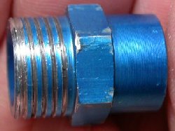 Here is the AN910-1D union I got from ACS. I had a 5/8-18 die, so I
threaded the AN910-1D for a nut. At first, the fitting wouldn't go into the die,
and it chewed up the end a bit. Then, I put the fitting and the die
into a bench vise and forced the fitting tightly into the die as I turned
the fitting, and then it fed in OK and made some marginally acceptable
threads. The major diameter of the threads isn't quite as large as it
should be for full depth thread engagement, but I think this will work,
especially if I use JB Weld or red Loctite on the threads. I ordered 3
of these AN910-1D fittings, so I may also try my hand at threading on a
lathe, and thread one for 9/16-18. A nut will go on these threads and
hold the union in the firewall. At each end of the union, there will
be a 1/8 NPT brass barbed hose fitting for the intake manifold vacuum line.
I decided this is the best way to get the vacuum line through the firewall,
with least amount of stainless steel drilling.
Here is the AN910-1D union I got from ACS. I had a 5/8-18 die, so I
threaded the AN910-1D for a nut. At first, the fitting wouldn't go into the die,
and it chewed up the end a bit. Then, I put the fitting and the die
into a bench vise and forced the fitting tightly into the die as I turned
the fitting, and then it fed in OK and made some marginally acceptable
threads. The major diameter of the threads isn't quite as large as it
should be for full depth thread engagement, but I think this will work,
especially if I use JB Weld or red Loctite on the threads. I ordered 3
of these AN910-1D fittings, so I may also try my hand at threading on a
lathe, and thread one for 9/16-18. A nut will go on these threads and
hold the union in the firewall. At each end of the union, there will
be a 1/8 NPT brass barbed hose fitting for the intake manifold vacuum line.
I decided this is the best way to get the vacuum line through the firewall,
with least amount of stainless steel drilling.
Oct 23 - Decided to try to redo my vacuum line firewall passthru better. Cut tight 9/16"-18 threads on another AN910-1D on the lathe. That was my first attempt at cutting threads on the lathe, and it went well. Put vacuum line firewall passthru together. Update web site 1.25 hr + 0.75 hr doc
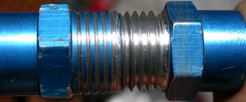 Two AN910-1D couplers held end-to-end. On LT is the AN910-1D I threaded with the 5/8-18 die. The threads did
not cut very deep because the metal wasn't quite a large enough diameter,
although I still had a hard time getting the die started over the fitting.
The 5/8-18 nut was kinda loose on that. On the RT is the one I did to
9/16-18 threads on the lathe. For my first attempt at cutting threads
on the lathe, it came out very well. I got the threads in, then took
the major diameter down a few thousandths at a time until the nut was a nice
snug fit. It was scary, running the bit in that close toward the spinning
chuck jaws. The nut is a perfect fit now; no play at all, and the nut
threads on by hand, with just some light wrenching needed for the last full
turn.
Two AN910-1D couplers held end-to-end. On LT is the AN910-1D I threaded with the 5/8-18 die. The threads did
not cut very deep because the metal wasn't quite a large enough diameter,
although I still had a hard time getting the die started over the fitting.
The 5/8-18 nut was kinda loose on that. On the RT is the one I did to
9/16-18 threads on the lathe. For my first attempt at cutting threads
on the lathe, it came out very well. I got the threads in, then took
the major diameter down a few thousandths at a time until the nut was a nice
snug fit. It was scary, running the bit in that close toward the spinning
chuck jaws. The nut is a perfect fit now; no play at all, and the nut
threads on by hand, with just some light wrenching needed for the last full
turn.
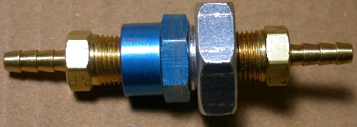 Here is the completed vacuum line firewall passthru. I'll be drilling
the firewall hole for it next. NOTE: found out later from
Dick Tasker that McMaster-Carr
carries brass bulkhead fittings which should work fine (44555K119 for
example on page 134 of the online catalog) without having to "roll your
own", as I did. Note, however, that 44555K119 is for 0.170" hole size
and I am using 1/8" ID silicone tubing.
Here is the completed vacuum line firewall passthru. I'll be drilling
the firewall hole for it next. NOTE: found out later from
Dick Tasker that McMaster-Carr
carries brass bulkhead fittings which should work fine (44555K119 for
example on page 134 of the online catalog) without having to "roll your
own", as I did. Note, however, that 44555K119 is for 0.170" hole size
and I am using 1/8" ID silicone tubing.
Oct 24 - received 4 hoses back from Southeastern Hose.
Oct 25 - Hooked up thermostat with new hoses. It seemed like a quite tight fit. I thought it was just the differences between my measurements and reality, and the fact that the hoses are so stiff. Eventually, I decided to measure the hoses, and figured out that I had specified lengths for "sealing surface to sealing surface", but they had made them that long as overall length (OAL). So, each hose is 1" too short. I rearranged the hoses, and used 2 of the longer ones where the shorter ones were supposed to go (between engine and thermostat). That left my 2 hoses between the thermostat and cooler 2" too short each. Will need to get new hoses for that. Hopefully, no hassles on getting that done. 1.75 hr
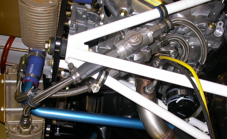
 Here is the oil cooler partially installed. I had to use the longer
(but 1" too-short) cooler-side hoses on the engine side of the thermostat,
so that left the 2 hoses on the cooler side of the thermostat 2" too short.
Waiting now for new hoses to finish this part. The hose stiffness and
Adel clamps between the hoses and the white engine frame tubes will hold it
all in place. The fwd side of the oil filter housing is the outlet, or
so I am told.
Here is the oil cooler partially installed. I had to use the longer
(but 1" too-short) cooler-side hoses on the engine side of the thermostat,
so that left the 2 hoses on the cooler side of the thermostat 2" too short.
Waiting now for new hoses to finish this part. The hose stiffness and
Adel clamps between the hoses and the white engine frame tubes will hold it
all in place. The fwd side of the oil filter housing is the outlet, or
so I am told.
Oct 26 - called Chris at Southeastern Hose. At first, he wanted to charge me for the replacement hoses, but after I reiterated that I'd specified in writing "sealing surface to sealing surface" on the lengths, he agreed to send me 2 replacement hoses today at no charge. NOTE: if you order hoses, they always want and expect OAL (Overall Length) specs.
Oct 30 - lay out and drill (drilling stainless steel sucks!) hole in firewall for engine vacuum line passthru. Install, seal, Loctite passthru. 0.75 hr
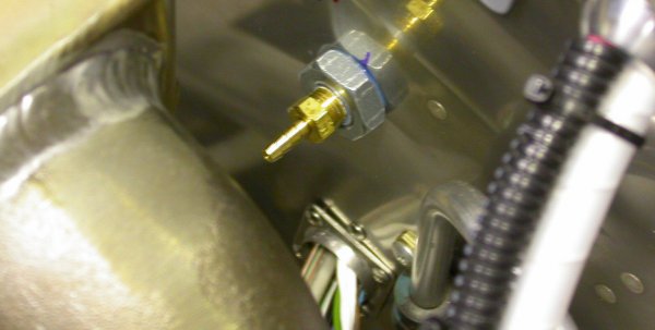 Here is the installed vacuum line firewall passthru fitting. The
vacuum line will pass through the down-crook in the inlet neck of the
intercooler (lower LT foreground in pic).
Here is the installed vacuum line firewall passthru fitting. The
vacuum line will pass through the down-crook in the inlet neck of the
intercooler (lower LT foreground in pic).
Oct 31 - Received replacement hoses from Southeastern Hose. Cleaned hoses, installed and torqued them. Install vacuum line to installed vacuum line firewall passthru. 2.5 hr
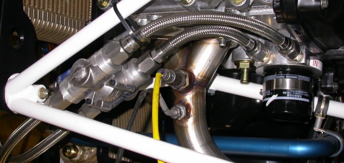
 Here is the oil cooler thermostat installed. Click on pic (best in
maximized window) for a larger
view. The thermostat is held firmly in place by the pairs of Adel
clamps on the upper outboard and lower inboard corners. The lower
outboard corner is firmly jammed into the vee formed by the engine frame
tubes, and the black heater hose held in place by a hose clamp protects the
frame and hose from each other. There are 2 more Adel clamps on the
lines between
the thermostat and the oil cooler. It's all quite rigid. To
duplicate this, assuming you have the same Eggenfellner RV-7A frame version
I do, you'll need these hoses (OAL measurement):
Here is the oil cooler thermostat installed. Click on pic (best in
maximized window) for a larger
view. The thermostat is held firmly in place by the pairs of Adel
clamps on the upper outboard and lower inboard corners. The lower
outboard corner is firmly jammed into the vee formed by the engine frame
tubes, and the black heater hose held in place by a hose clamp protects the
frame and hose from each other. There are 2 more Adel clamps on the
lines between
the thermostat and the oil cooler. It's all quite rigid. To
duplicate this, assuming you have the same Eggenfellner RV-7A frame version
I do, you'll need these hoses (OAL measurement):
engine supply = 8"
engine return = 11"
cooler supply = 15.5"
cooler return = 12.75"
Southeastern Hose can cut your existing hoses to these lengths, assuming yours are long enough to begin with.
Thus ends another month of work. Go to November, 2006 engine.
BACK TO MY RV BUILDER'S HOME
BACK TO BRIAN'S HOME