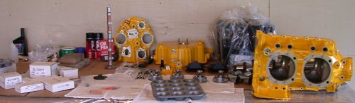
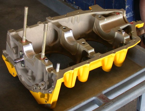
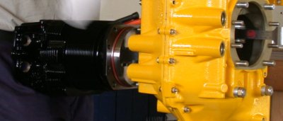
 Here's what
we started with.
Here's what
we started with.BUILDING THE SUPERIOR SL-360 ENGINE
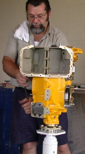
This page is based on pictures and notes I took at a "Superior SL-360 Engine Kit Buildup" seminar at the 2003 Oshkosh AirVenture. The seminar was presented by Bill Peterson of Superior Air Parts and Bob Honig of Eagle Engines.
SEE ALSO: Kathleen Evans, a 60 year old lady artist doing her first project, went with the Eagle engine. See here for her pics & details on her experience with it.
The following is a quick overview of Superior and Eagle. See their web sites (linked above) for more exact details on their products and services.
Superior is a company that makes certificated replacement Lycoming engine parts, and they also make non-certificated complete engines for experimental planes. Their engine is a 180 HP exact duplicate of the Lycoming 360 cubic inch engines, with Superior's added features. They make 2 versions of the 360; an SL and an XP. The SL-360 can be bought as a build-it-yourself-at-home kit. The XP-360 is assembled by Superior. They also have programs where you can go to Texas and supervise them building your XP-360 ($500), or they can supervise you building your own XP-360 at their plant ($1000). Superior is located in Coppell, Texas, near Dallas/Fort Worth. You save about $500-700 by building your own SL-360 at home. You have to pay them $1000 to go to their place to build your own XP-360, so personally I don't know why anyone would want to do that. Maybe they start with a lower "unassembled" price; check with Superior. If you build your own SL-360, it has a 1 year warranty on parts only. At the class, they said the XP-360 has a 3 year warranty, but their web site says it's one year, with an optional 3 year warranty at extra charge. Also, their web site says the warranty starts the day the engine is shipped. I'm not real clear on just what (if any) difference there is (in parts) between an SL-360 engine and an XP-360 engine. Check with Superior. The SL-360 doesn't come with any assembly instruction manual, although they said they are considering making an assembly video (GREAT idea!). You can also get the XP-360 with an optional composite sump that saves 8 pounds and costs $1,000.
Eagle is a partner with Superior. They are located in Redding, CA, and they sell the same SL-360 and XP-360 engines and parts at the same prices as Superior. So, you would buy from whichever source is closer to you. Eagle also makes a custom-built version of the 360 they call the Xtreem-360. They add cylinder flow matching, 3-angle valve job, and Parkerized internal gear train. They also offer custom engine paint and various ignition options. The Xtreem-360 engines have a 2 year warranty on parts & labor. Bob said in class that his warranty starts the day the engine is started in the plane. He also said he balances his reciprocating parts to within 0.2 grams, while the Superior XP-360 parts are balanced to within 2 grams. I don't know what, if any, balancing is done on the SL-360 parts. The crank is nitrided and micropolished, but not shot-peened. The rods aren't shot-peened. Bob says titanium rods are not used in the aircraft industry. Angle-valve cylinders are not currently available, but Bob says they will be available early January, 2004.
Check with Superior and Eagle for all the details and fine print on all the options I've mentioned above.
For the class, we were watching Lou Pierard, Eagle's shop chief, assemble a customer's Xtreem-360 with 10:1 pistons (the max they recommend is 9.5:1, but they'll build it any way you want it), estimated at 220-225 HP. Bob said the 10:1 will wear the cylinders faster, but the customer was willing to accept a 1 year warranty to get the 10:1 he wanted. This is also another reason I suspect they don't offer angle valve cylinders; if this customer was willing to go to 10:1 pistons for max HP, surely he would have also gone for angle valves.
Here is how you put a Lycoming or Superior 360 engine together. Keep in mind that the micrometer work was already done before coming to OSH, so clearances were already set up & measured. The cylinders were fully assembled. All the studs were installed. I don't know how much, if any, of that work is done for you if you buy an SL-360 to assemble yourself; I suspect none of it is done. To build one of these engines, you need to have the part number 602947 Lycoming Overhaul Manual and the #1037 Table Limits manual.
I will apologize once in advance for any blurry pictures. With an automatic digital camera, sometimes it just doesn't get the focus right. I tried to make the pictures large enough to have good detail, and small enough so loading time is reasonable. If you need an original, uncropped, unresized version of a picture for more detail, let me know.
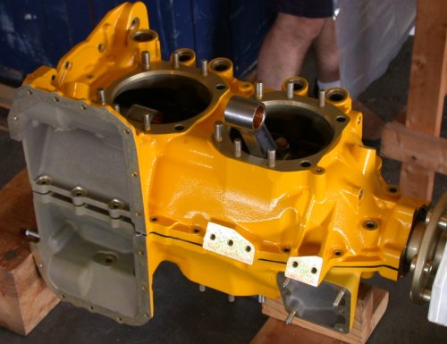
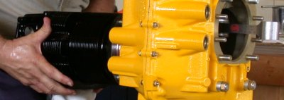
Here's what
we started with.
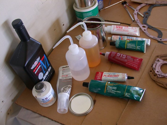 Here's what we used for lubricants and sealers. The little plastic bottles
are very handy. One contains motor oil and the other contains denatured
alcohol for keeping things clean. The metal can contains a 50/50 mixture
of STP and motor oil. You can read the labels on the other items.
Here's what we used for lubricants and sealers. The little plastic bottles
are very handy. One contains motor oil and the other contains denatured
alcohol for keeping things clean. The metal can contains a 50/50 mixture
of STP and motor oil. You can read the labels on the other items.
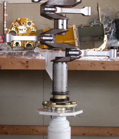
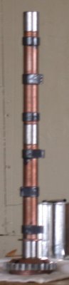
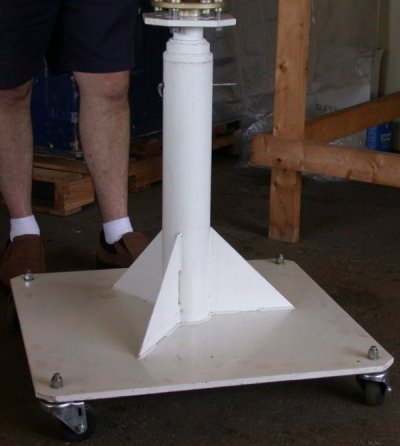 This is
their engine stand.
This is
their engine stand.
Before beginning, you should use a thread-chaser on all the stud threads. If you haven't used a thread-chaser, it's like a thread-cutting die, except it's made for just cleaning up existing threads.
Wash (with denatured alcohol), dry, and use Permatex #2 on the galley plugs. Install the plugs.
Snap the main and rod bearings into place. You need to mike the crank and bearings to make sure you have the right clearances. They do NOT recommend Plasti-Gage. The engine Lou put together for us had all that already done back at the shop.
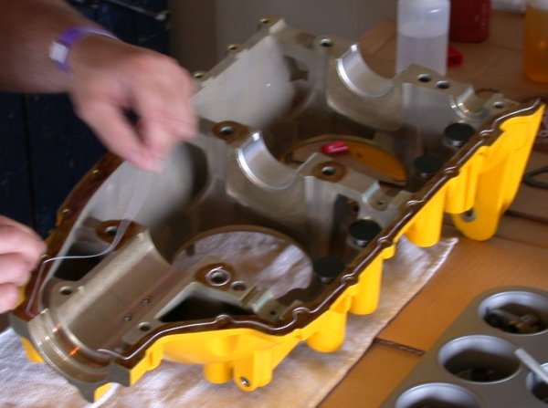
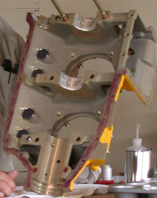
Put Permatex Form-A-Gasket onto the left case half, and let it get tacky for about an hour. Look closely at the pictures below to see where it goes - just on the mating surfaces.
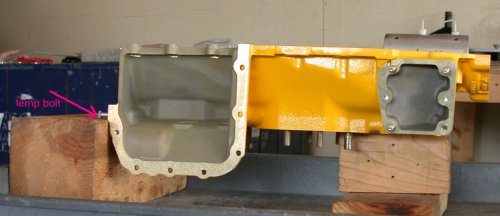 Lay the case half onto a wooden stand. A couple cheap
bolts in the end of the case will help the case half lay flat.
Lay the case half onto a wooden stand. A couple cheap
bolts in the end of the case will help the case half lay flat.
 Put the 2 studs and 4 o-rings into the
right case half.
Put the 2 studs and 4 o-rings into the
right case half.
Put moly engine assembly lube onto the lifter bodies and drop them into place.
Warm and carefully stretch the oil seal over the crank flange.
Bolt engine stand base onto crank, and stand crank up on engine stand.
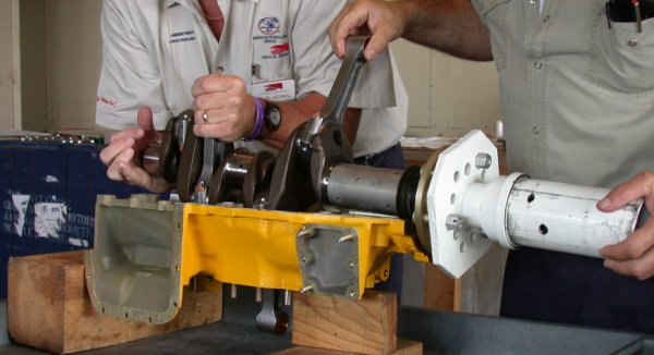
Use a 50/50 mix of engine oil and STP on the rod bearings and crank journals.
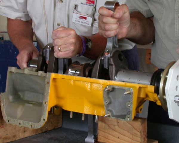
 Put the rods onto the crank
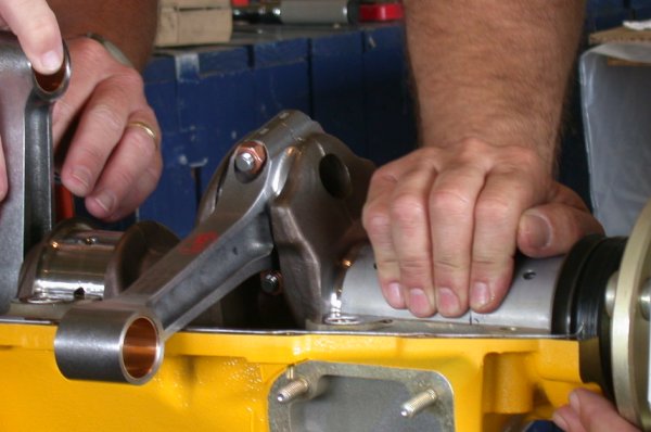
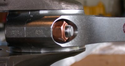 Oil the rod bolts with plain oil, and apply the rod bolt
nuts. The nuts go on with what may look like an integral washer facing
OUT.
Oil the rod bolts with plain oil, and apply the rod bolt
nuts. The nuts go on with what may look like an integral washer facing
OUT.
Torque rod bolts to 40 ft-lb.
 Lay silk thread onto the
left case half, in the middle of the
Form-A-Gasket you applied earlier. Let the ends hang out over the end of
the case. The silk thread is your gasket. You can use ordinary
sewing thread, but make sure it's silk. Be sure you get it around the 4
through-stud holes as shown in the picture.
Lay silk thread onto the
left case half, in the middle of the
Form-A-Gasket you applied earlier. Let the ends hang out over the end of
the case. The silk thread is your gasket. You can use ordinary
sewing thread, but make sure it's silk. Be sure you get it around the 4
through-stud holes as shown in the picture.
AUGUST, 2004 UPDATE: I received the following email, so I am putting the info here for your education. I don't know either way; I was just taking pics and notes at a seminar by an engine builder who specializes in building these engines:
Here is a link to one article about this practice and about failures that have occurred because of this practice
Just wanted you to know what I had learned and pass it on to you in consideration of your safety.
Thanks again for your web page. It is really a good review of building the Lycoming.
Here is a forward of the email from Evan. I belong to a Yahoo Lycoming Engine Discussion Group. It was to the group that this email was sent in response to my query.
A fellow from Mattituck participates on the group and he is very knowledgable and informative. His name is Mahlon. I will also forward his response.
Your Fellow RV Enthusiast,
Ned,
Lycoming Service Instruction 1125B deals with this. It allows the use
of 515 or silk thread. If it were me, I would use silk thread. We
haven't seen a lot of success with anyone using just 515. The Lycoming
factory, at one time, was using the 515 method and stopped. To the
best of my knowledge, they stopped due to lack of success as well.
Maybe some of the others, in the group, have a different experience
using the 515 method and will relate it. According to Lycoming, you
should never put sealant or thread between the bearing bosses on the
case and I would respect that position and definitely agree with it.
As Bill from Superior suggested, the fit of the thru bolts is what is
supposed to seal the area, on a body fit thru bolt case. This fit is
also what is supposed to prevent crankcase fretting, at those
surfaces, by helping to provide some of the rigidity that is necessary
at the bearing bore to keep them stationary, while the engine is
running. In my opinion putting anything in between the bearing bores
may cause a lack of rigidity and help allow fretting which could
eventually cause excessive oil leaks, bearing bore dimensional change
and possible bearing shift.
Good Luck,
Mahlon
Ned,
I concur with Mahlon regarding his sealant comments. I have no
experience with Loctite 515, but have used RTV 102 since it was first
recognized and approved by Lycoming. Properly applied, RTV 102 is an
excellent sealant. I use one strand of "00" silk thread
as "insurance" even though it is not necessary according to
Lycoming. I do not apply any sealant or thread to the main bearing
saddle surfaces. The RTV must be applied as stated by Lycoming to
only one case half and the application must be thin and translucent,
being careful to wipe the inside edge and keep the sealant away from
the cam journals as pictured in Lycoming Instruction 1125B. Also,
just prior to applying any sealant be sure to clean the mating
surfaces with a "fast dry" solvent such as Acetone or MEK. When
using RTV, one must assemble the parts quickly and snug the attach
hardware before the RTV sets up or dries.
Evan Yearsley
Engine Production Manager
Superior Air Parts, Inc.
Lay forward main bearing into place in its locating dowels. Make locating marks on the bearing and case. This will make assembly later much easier.
Oil the inner end of the oil seal. Don't get the oil all over the seal.
Put 50/50 mix onto the forward crank main bearing and journal and put both bearing halves over the crank journal. I don't know why they didn't just snap this bearing into place in the case and lay the crank into it, like they did with the other main bearings, but I didn't think then to ask, and this is how they did it.
Don't get oil in the area where the oil seal will go in the case.
Use Pliobond on the outer end of the oil seal. Make sure the seal is clean and dry before doing this.
Put the forward main bearings onto the crank, and very carefully, with a helper, lower the crank into place on the case half.
 Be
very careful to get the main bearing fully seated into its locating dowels
(remember those marks you made?) and make sure the oil seal is sitting properly
in its place in the case.
Be
very careful to get the main bearing fully seated into its locating dowels
(remember those marks you made?) and make sure the oil seal is sitting properly
in its place in the case.
 Put moly cam lobe lube onto the cam lobes and the lifter bases,
and lay the cam into place.
Put moly cam lobe lube onto the cam lobes and the lifter bases,
and lay the cam into place.
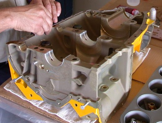
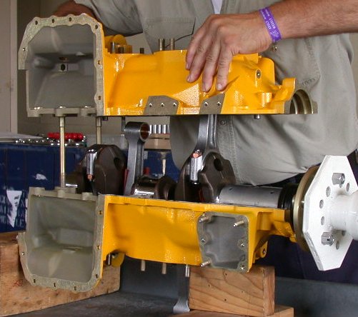
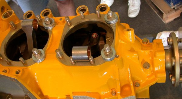
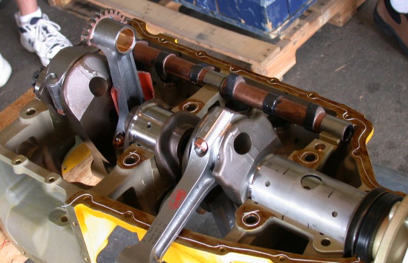 This is
a good picture that shows a lot of the details, so I made it big. You can
see clearly where the Permatex goes and doesn't go. You can see where and
how the thread goes. You can see the rod bolt nut orientation. You
can see the crank in place, and you can see the cam in place. You can see
the locating marks for the big forward main bearing. You can see the
pieces of rubber sheet used to hold the rods vertical for placing the other case
half. You can see how that huge front main bearing lays in place.
This is
a good picture that shows a lot of the details, so I made it big. You can
see clearly where the Permatex goes and doesn't go. You can see where and
how the thread goes. You can see the rod bolt nut orientation. You
can see the crank in place, and you can see the cam in place. You can see
the locating marks for the big forward main bearing. You can see the
pieces of rubber sheet used to hold the rods vertical for placing the other case
half. You can see how that huge front main bearing lays in place.
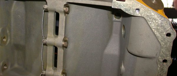
 Put Loctite 515 onto the
right case half's outer mating
surfaces. Don't get it anywhere else.
Put Loctite 515 onto the
right case half's outer mating
surfaces. Don't get it anywhere else.
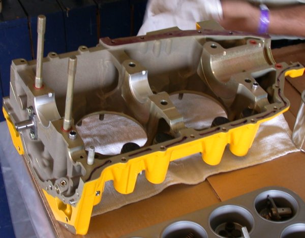
 This is
what the Loctite on the right case half should look like.
This is
what the Loctite on the right case half should look like.
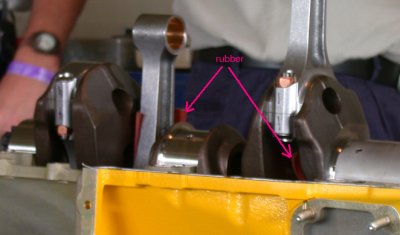 Put pieces of rubber between the rods and the crank, so the rods
will stand up straight by themselves.
Put pieces of rubber between the rods and the crank, so the rods
will stand up straight by themselves.
Double-check everything very carefully before closing up the cases. Use a second set of eyes.
 Put the
cases together.
Put the
cases together.
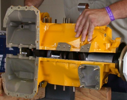
Be sure to remove the rubber you put around the rods!
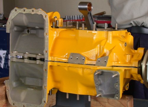
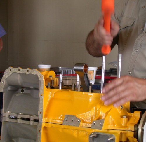 Put Loctite 515 onto the centers of the 4 through-studs and tap
them into place.
Put Loctite 515 onto the centers of the 4 through-studs and tap
them into place.
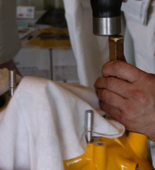 With a new case,
the thru-studs may be rather tight, and may
require using a brass drift. Drive them in at least until a few threads
are visible on the other side. Put lint-free rags over the cylinder holes
before doing this, so you don't knock any crud or brass chips down into the cases.
With a new case,
the thru-studs may be rather tight, and may
require using a brass drift. Drive them in at least until a few threads
are visible on the other side. Put lint-free rags over the cylinder holes
before doing this, so you don't knock any crud or brass chips down into the cases.
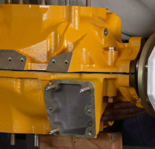 Put in the
main bearing bolts and the case perimeter bolts and snug them up.
Put in the
main bearing bolts and the case perimeter bolts and snug them up.
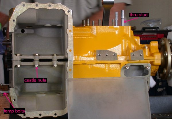 Note that the perimeter bolt nuts inside the sump area are
castle nuts. These must be safetied before installing the sump.
Note that the perimeter bolt nuts inside the sump area are
castle nuts. These must be safetied before installing the sump.
 Make a Sharpie pen mark on the case by the case perimeter bolt
near the cam gear, to remind you to make sure this nut gets installed, torqued,
and safetied.
Make a Sharpie pen mark on the case by the case perimeter bolt
near the cam gear, to remind you to make sure this nut gets installed, torqued,
and safetied.
Wipe off excess Permatex around the perimeter with denatured alcohol.
 Oil the through-stud threads, and put a cheap temporary flat
washer and nut onto the bottom side. Tighten up the nuts to pull the
through-studs through the case, until they are close to even.
Oil the through-stud threads, and put a cheap temporary flat
washer and nut onto the bottom side. Tighten up the nuts to pull the
through-studs through the case, until they are close to even.
Make sure the crank turns freely.
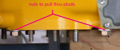
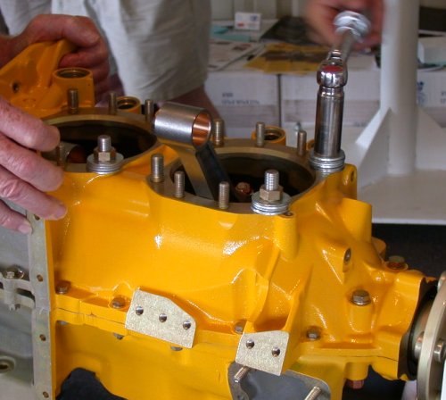 Put several washers and a nut onto the top of each
through-stud. Use them to snug up the through-studs.
Put several washers and a nut onto the top of each
through-stud. Use them to snug up the through-studs.
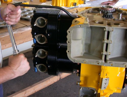
Start torquing the case bolts.
 Tighten them to 30
ft-lb. Start with the mains in the center, then do the perimeter
bolts. See the overhaul manual for the proper sequence.
Tighten them to 30
ft-lb. Start with the mains in the center, then do the perimeter
bolts. See the overhaul manual for the proper sequence.
Make sure the crank turns freely.
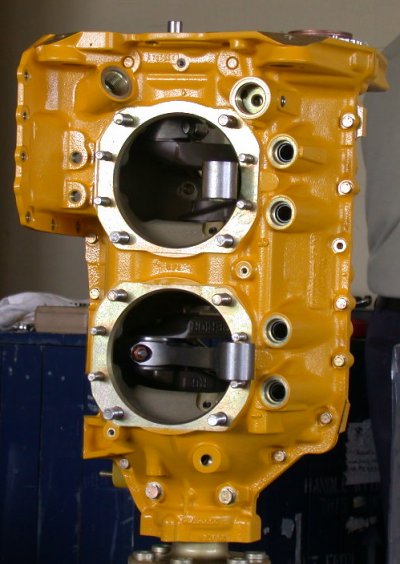
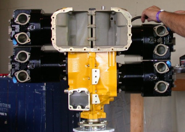
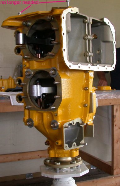 Stand the short block assembly up on the engine stand.
 Recheck all the torque values.
 Lou finalizing the torque on all the case bolts.
 Don't
forget that nut that's tucked away.
Don't
forget that nut that's tucked away.
![]() Once
you pull the thru-studs through enough, install the spacers and the proper nuts.
Once
you pull the thru-studs through enough, install the spacers and the proper nuts.
 Remove the center
through-stud nuts and oil all the cylinder stud
threads.
Remove the center
through-stud nuts and oil all the cylinder stud
threads.
????? Put 50/50 mix on the cylinder locating pins.
Clean the #1 cylinder base and put the cylinder o-ring in place.
Pull the piston PART-way out of the cylinder. Do this carefully, making sure you don't pull it out so far that the rings come out. If you slip and the rings do come out, be sure to take your time and very carefully put them back in, using a proper ring compressor.
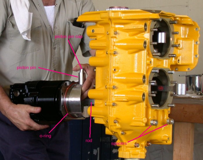 Pull the piston pin part-way out of the piston and lube it with
the 50/50 mix. If you haven't worked on aircraft engines, and you've only
worked on auto and motorcycle engines, you might be as surprised as I was to
find that aircraft engines don't use piston pin retaining clips. They use
aluminum caps that go on the end of the piston pin, and the caps ride on the
cylinder walls.
Pull the piston pin part-way out of the piston and lube it with
the 50/50 mix. If you haven't worked on aircraft engines, and you've only
worked on auto and motorcycle engines, you might be as surprised as I was to
find that aircraft engines don't use piston pin retaining clips. They use
aluminum caps that go on the end of the piston pin, and the caps ride on the
cylinder walls.
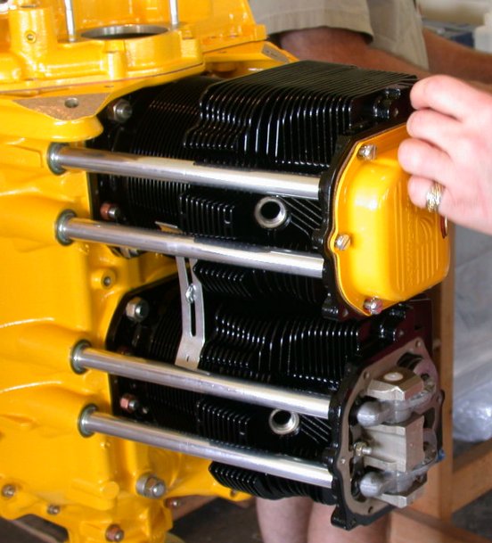
 Put the cylinder (with the piston protruding from the base) over
the rod and push the piston pin through the rod.
Put the cylinder (with the piston protruding from the base) over
the rod and push the piston pin through the rod.
 Carefully push the cylinder into place on the case, over the
studs and locating pins, until the cylinder base is against the case.
Carefully push the cylinder into place on the case, over the
studs and locating pins, until the cylinder base is against the case.
Put the 1/2" nuts on the cylinder studs.
Snug up stud and through-stud nuts.
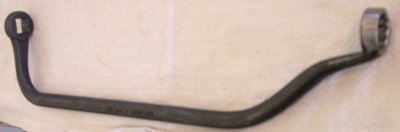 Use a special curved box-end wrench to get at the cylinder stud
nuts. This one is 1/2" square drive on one end.
Use a special curved box-end wrench to get at the cylinder stud
nuts. This one is 1/2" square drive on one end.
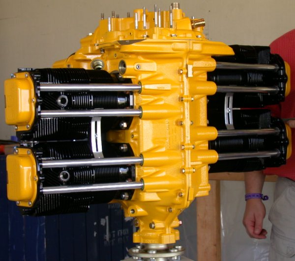
 Repeat with the remaining cylinders.
Remove spark plug caps from cylinders.
 Put on the smaller cylinder base nuts and torque all the cylinder stud nuts to 30 ft-lb.
Turn engine around the crank, and make sure it still turns freely.
If torqueing a nut and it causes the through-stud to squeek, or not pull through smoothly (as happened here), or if you encounter any other problems or anomalies in the building, do not just continue. Stop, take it apart, and find the source of the problem.
Be careful the wrench does not slip off the nut when torqueing. The outside of the box end of the wrench may need to be ground down a bit for clearance.
Recheck the torque on the main bearing studs to 30 ft-lb
Torque all 1/4" perimeter bolts to 110 in-lb.
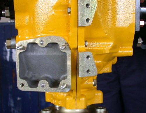 Note different orientation of some perimeter bolts.
Make sure the engine still turns freely around the crank
 Line up the safety wire holes in the 3 perimeter bolts with
castle nuts in the sump area, and safety the nuts.
Line up the safety wire holes in the 3 perimeter bolts with
castle nuts in the sump area, and safety the nuts.
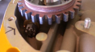
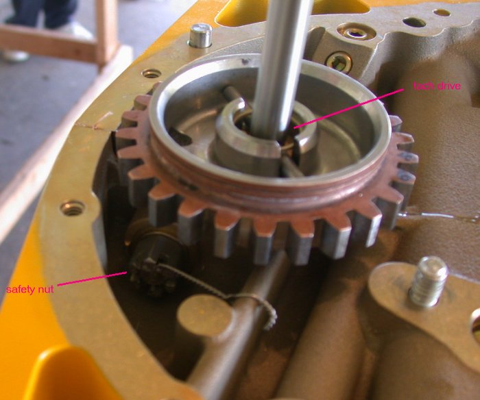 Also, safety the nut on
the through bolt behind the cam drive gear. Personally, I think cotter
pins are far quicker and easier and, IMHO, more reliable than safety wire in
this sort of application. But we did it with safety wire here.
Also, safety the nut on
the through bolt behind the cam drive gear. Personally, I think cotter
pins are far quicker and easier and, IMHO, more reliable than safety wire in
this sort of application. But we did it with safety wire here.
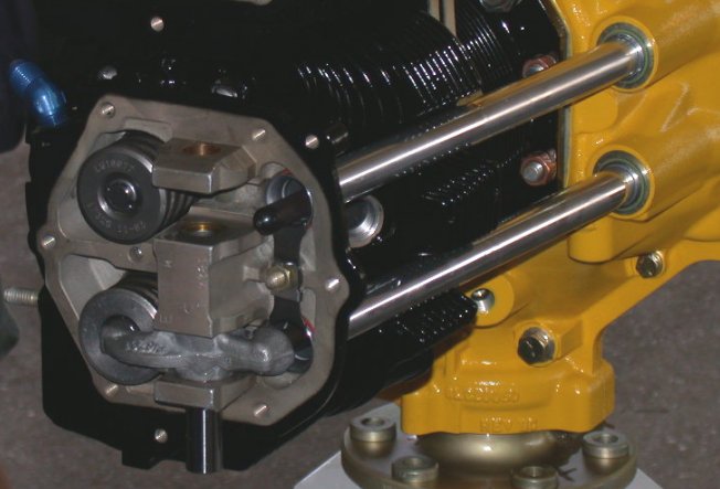
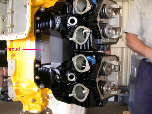 Install
on the cylinder fin shrouds.
Install
on the cylinder fin shrouds.
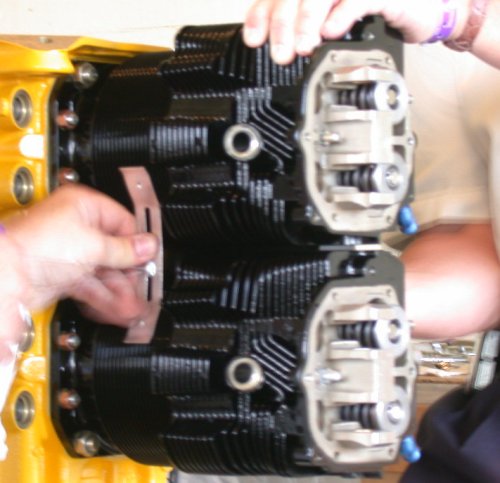 Put
safety wire on the rod that holds them, and use the safety wire to pull the rod
tight through the clamping bar.
Put
safety wire on the rod that holds them, and use the safety wire to pull the rod
tight through the clamping bar.
 Install the pushrod cover tubes. Be sure to lube the tube o-rings with
silicone to help
them slip into place.
Install the pushrod cover tubes. Be sure to lube the tube o-rings with
silicone to help
them slip into place.
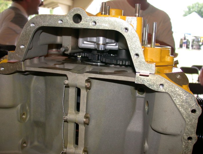
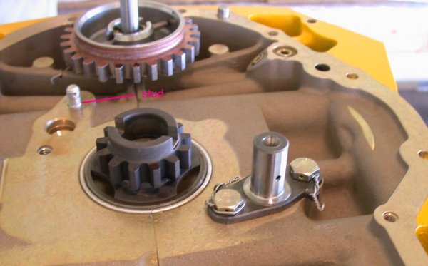 Install and safety the posts for the idler gears. Make sure the stud
holding one of the idler gear posts is not too high. It must be high
enough to get the safety wire or cotter pin through it, but no higher than
necessary.
Install and safety the posts for the idler gears. Make sure the stud
holding one of the idler gear posts is not too high. It must be high
enough to get the safety wire or cotter pin through it, but no higher than
necessary.
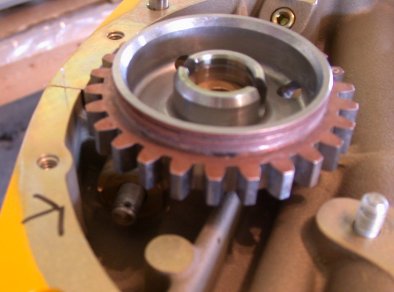
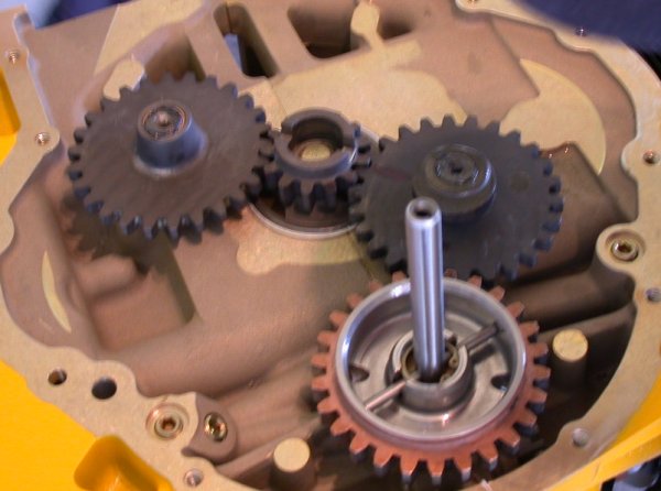 Lube
idler gear posts with moly engine assembly grease, and put on the idler
gears. Make sure the timing marks line up on the idler gears. This
is important.
Lube
idler gear posts with moly engine assembly grease, and put on the idler
gears. Make sure the timing marks line up on the idler gears. This
is important.
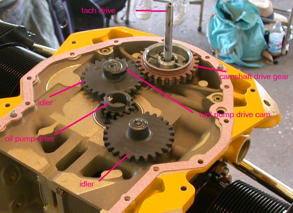 Here's what all the idler gears do.
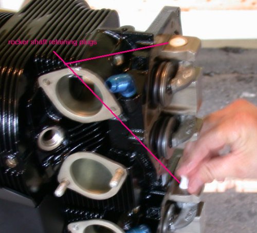
Install tach
drive shaft and its retaining clip with circlip. The circlip holds the
tach shaft spacer under it.. Install the circlip with the flat side out.
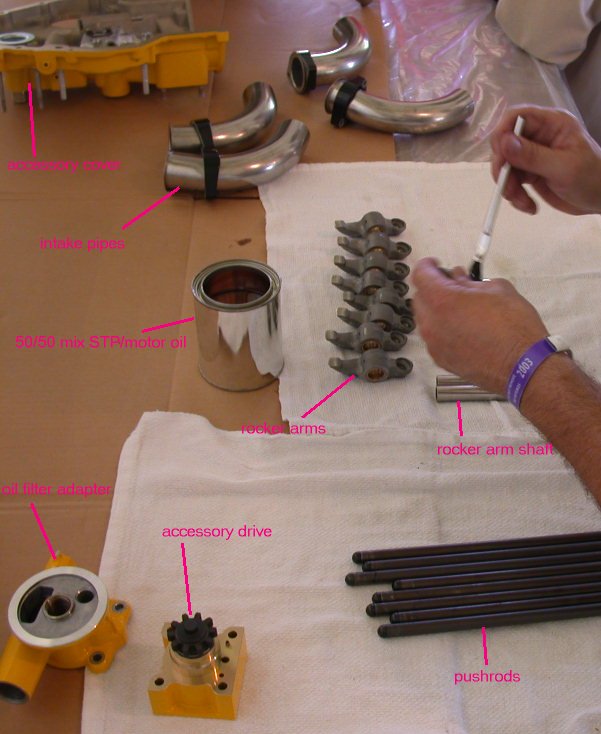 Lube the
pushrods, rocker arms, rocker arm shafts, and rocker arm shaft bushings with
50/50 mix.
Lube the
pushrods, rocker arms, rocker arm shafts, and rocker arm shaft bushings with
50/50 mix.
Put a screwdriver (gently-!) into the #1 cylinder spark plug hole, and rotate the engine until the piston is at Top Dead Center (TDC) of the compression stroke (both rocker arms loose on valve stems).
Install the pushrods in the pushrod tubes.
Put moly grease on the ends of the valve stems.
 Put
the rocker arm in place and push the rocker arm shaft through its bushings.
Put
the rocker arm in place and push the rocker arm shaft through its bushings.
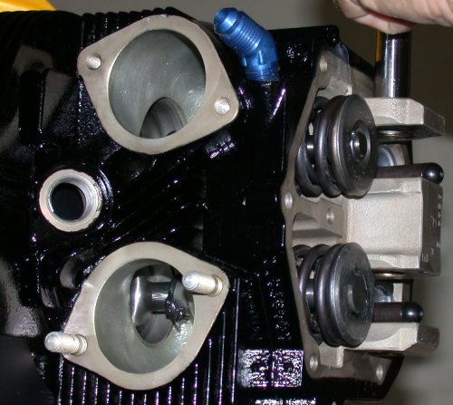 Here's a peek inside the port, showing the valve and the moly assembly grease
around the stem.
Here's a peek inside the port, showing the valve and the moly assembly grease
around the stem.
Make sure a 0.030 feeler gage will go between the rocker arm and the valve stem. Make sure a 0.075 feeler gage will NOT go between the rocker arm and the valve stem. The hydraulic lifter will handle this range of adjustment. If you don't get the go/no-go clearances described here, get longer/shorter pushrods until you do.
Repeat for cylinders 3, 2, 4.
 Install the rocker arm shaft end buttons.
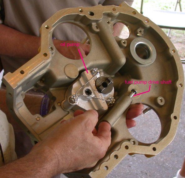
Install oill pump into accessory cover.
 Clean
the accessory cover surface.
Clean
the accessory cover surface.
Put moly grease on fuel pump drive cam
Put a small dab of silicone sealer at the 2 ends and center of the accessory cover mating surfaces on the cases.
Lay the rear cover gasket in place.
Moly lube the fuel pump drive shaft.
Make sure everything is OK under the accessory cover area before installing it. Use a second set of eyes.
 Put the accessory cover in place, making sure the fuel pump drive shaft lines up
with its driving cam.
Put the accessory cover in place, making sure the fuel pump drive shaft lines up
with its driving cam.
Trim the ends of the accessory cover gaskets.
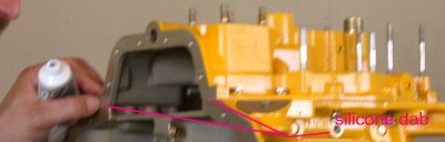 Put a dab of silicone sealer at the ends of the accessory cover gaskets.
 Install the valve covers and gaskets. Tighten valve cover bolts until the
gasket just starts to squeeze out; no more.
Install the valve covers and gaskets. Tighten valve cover bolts until the
gasket just starts to squeeze out; no more.
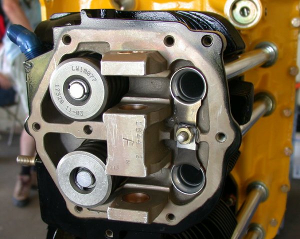
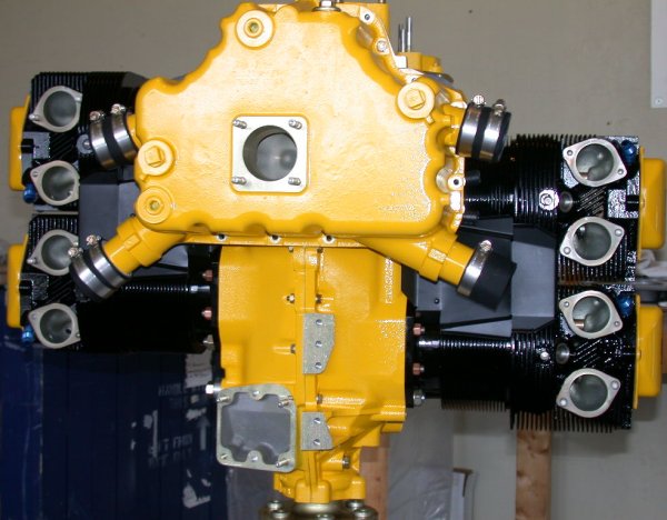
 Valve covers and shrouds all installed.
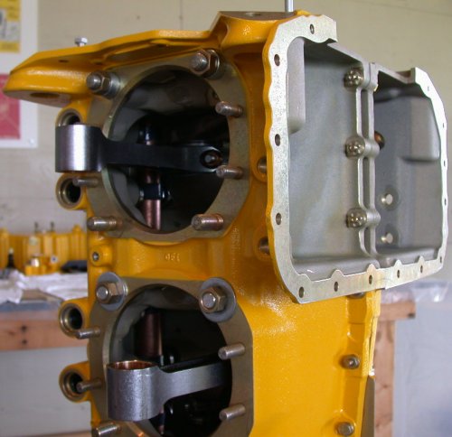
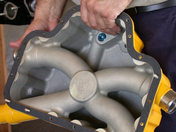 Put on the
sump gasket.
Put on the
sump gasket.
 Install
the sump, making one last check that the perimeter nuts under the sump cover are
safetied.
Install
the sump, making one last check that the perimeter nuts under the sump cover are
safetied.
 Put
teflon pipe paste (never use teflon tape) onto the cylinder drain plug threads,
and install the plugs snugly.
Put
teflon pipe paste (never use teflon tape) onto the cylinder drain plug threads,
and install the plugs snugly.
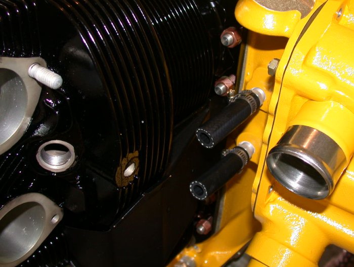 Put
the rubber tubing and hose clamps onto the cylinder drain plugs.
Put
the rubber tubing and hose clamps onto the cylinder drain plugs.
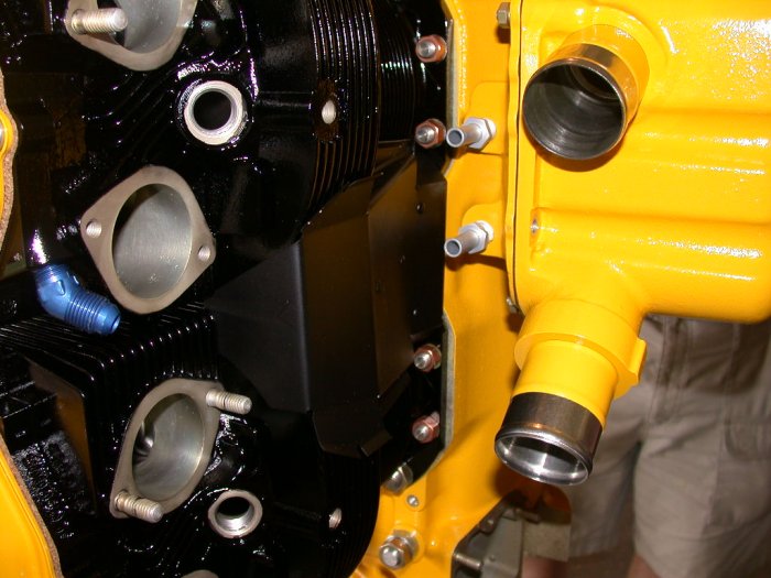
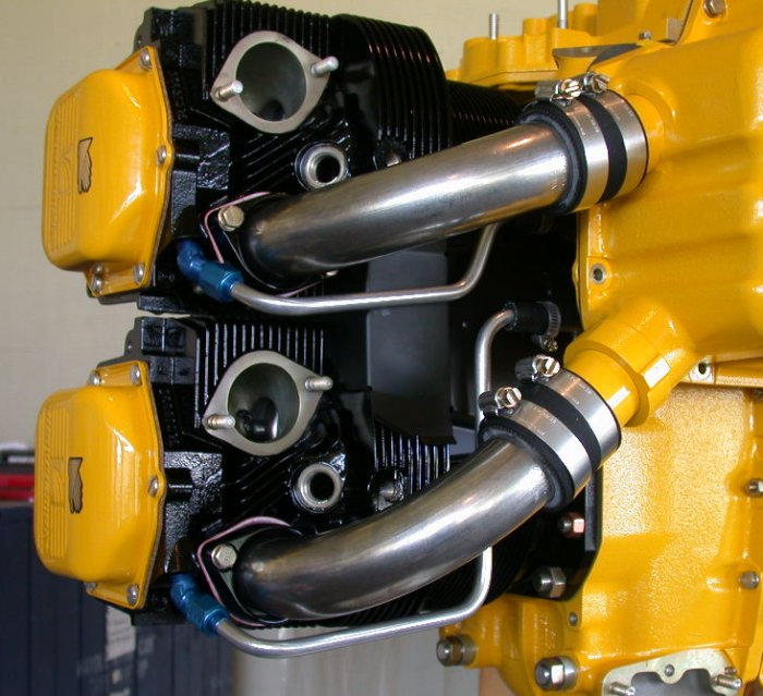
 Install the
intake hoses and hose clamps. Use as small a clamp as possible, so you
don't have annoying tails coming off the clamps.
Install the
intake hoses and hose clamps. Use as small a clamp as possible, so you
don't have annoying tails coming off the clamps.
Put the intake port gaskets in place. They go in dry.
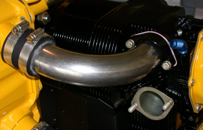 Install the
intake pipes between the intake hoses and the intake ports on the
cylinder. Make sure the pipe flange sits properly into the port.
Wiggle the pipe to ensure it is seated well.
Install the
intake pipes between the intake hoses and the intake ports on the
cylinder. Make sure the pipe flange sits properly into the port.
Wiggle the pipe to ensure it is seated well.
Torque the intake port clamp bolts to 110 in-lb. You will need a thin wall swivel socket to do this.
Place a hose clamp on the outer end of the cylinder drain rubber tubing.
Lightly oil the cylinder drain AN fittings, and install the aluminum drain tubing.
 The
4 cylinder drain tubes are not all alike; be sure you put the right one in the
right place.
The
4 cylinder drain tubes are not all alike; be sure you put the right one in the
right place.
Make sure the cylinder drain tubing fit is not forced, then tighten the AN nuts. You may need to bend the tubing slightly or turn the AN fittings a bit to get a good non-forced fit.
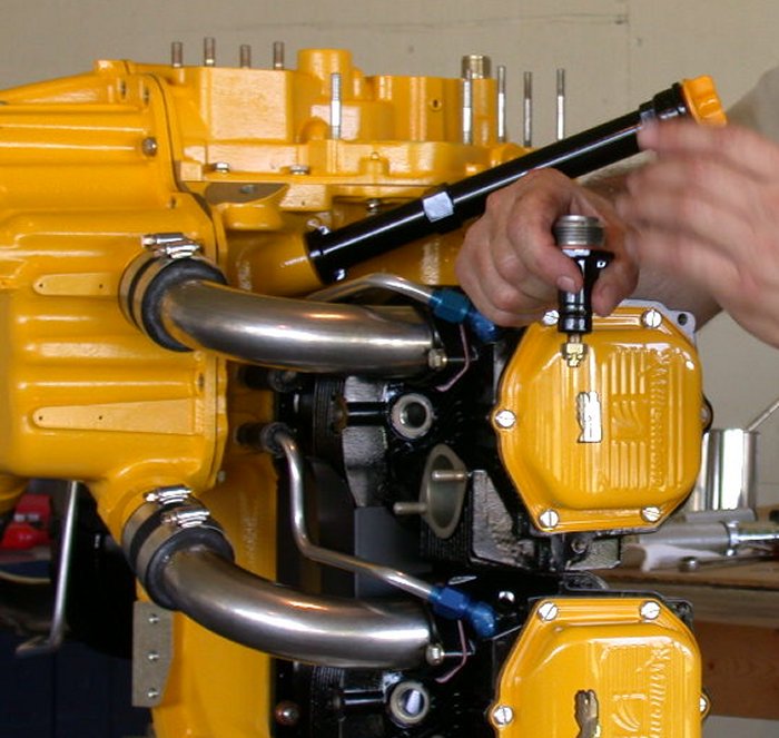
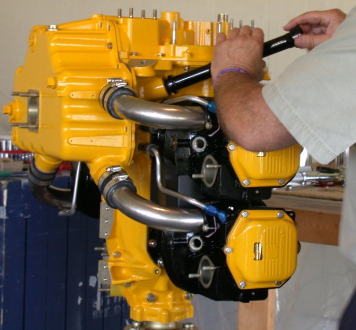 Put silicone onto the threads of the oil filler tube, and screw that in.
 Put teflon
paste onto the threads of the oil pressure sending unit, and screw that in.
Put teflon
paste onto the threads of the oil pressure sending unit, and screw that in.
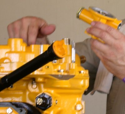 Install
the oil filter adapter.
Install
the oil filter adapter.
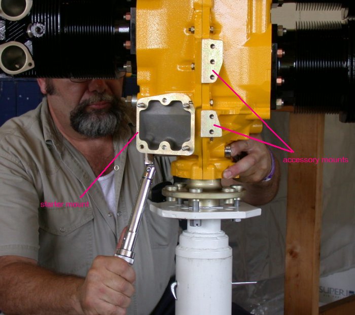
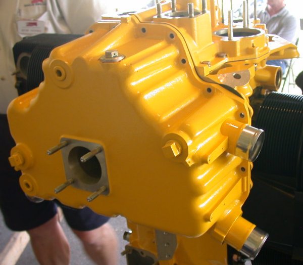
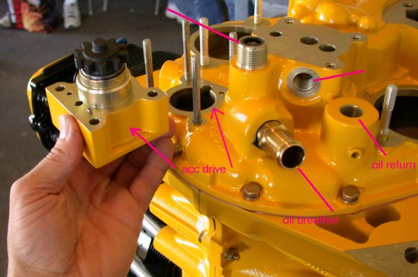 This is where the accessory drive gets mounted..
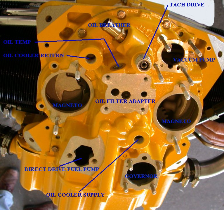 And here is a picture showing where all the other things mount on the accessory
cover.
And here is a picture showing where all the other things mount on the accessory
cover.
That's about it, or at least that's as far as we went in the class.
Make sure you pre-oil any new engine you are starting for the first time!
BACK TO MY RV BUILDER'S HOME
BACK TO BRIAN'S HOME