I am still working toward getting the
engine ready to start, and getting the engine
wired for that.
Nov 6 - Still haven't gotten the
console I ordered from
Aircraft Extras, so I emailed
Rich to find out why. Been feeling too sick to work on plane (got a
cold).
Nov 8 - Talked to Bryan at
Xtreme
Products about the console and sorted out details. He'll get me out my
console and quadrant ASAP.
Nov12 - While working on other
things, started fretting again about those
wing bolts. Reviewed emails between me and Van's about it.
Redid all the measuring and checking of fit of NAS and hardware store bolts.
Decided to start ordering some reamers that I will probably need for this.
My thinking is that, as long as the NAS bolts end up being a tight,
hammer-in fit, I will be OK. I think running a reamer through at least
some of those bolt holes is inevitable. After going to bed, had an
epiphany just before falling asleep. I suddenly realized the best
throttle quadrant configuration for how I will be using it for throttle and
wastegate control will be to have it configured as if for a twin engine
plane. 1.0 hr
Nov 13 - Called Bryan and told
him to change order configuration. He will send me a quadrant with
2 throttle levers. He also said quadrant maker wants 5x normal
price to give me custom labeling on the quadrant, so forget that!
Nov 14 - Ordered from
MSC
- 4 reamers for each bolt
diameter, 0.0005" or 0.001" apart, in sizes a couple thousandths smaller
than each NAS bolt diameter. I am measuring 0.4350" on the 7/16" NAS
bolts and 0.2475" on the 1/4" NAS bolts.
Nov 15 - received MSC reamers
Nov 16 - clean up upper gear
mount frame holes from front with Dremel tool. Clean up lower gear
mount frame holes by carefully inserting reamers through spar holes from
rear. For the 1/4" bolt holes, I had 0.2445, 0.2450, 0.2455, and
0.2465" reamers. For the 7/16" holes, I had 0.4310, 0.4320, 0.4330"
reamers. Even the largest is still an easy slip fit through the spar
holes, so no cutting there. I started with the smallest and worked my
way up to the largest, protecting the spar holes as I went along. I
need to go about 0.001" more on each size. I only needed to do this on
the bottom 4 holes on each side, as I was able to enlarge the gear mount
frame holes from the front on the upper holes. It's been unseasonably
warm all month, especially the last week; in the 50s or better. It was
67 degrees today at LEB!! Much better than the usual below-freezing
that November usually is.
3.25 hr
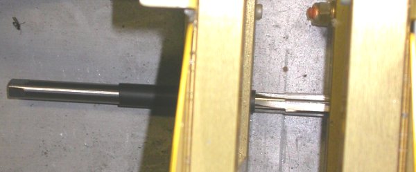
Reaming one of the gear mount frame holes on the lower RT side. The
black is heatshrink I slid into the aft spar hole to help stabilize the
reamer and to protect the spar hole. It was a perfect snug slip fit
between the spar hole and the reamer shaft. I ground a square end onto
each reamer and turned it slowly & carefully by hand with a small adjustable
wrench, while pushing the reamer fwd into the gear mount frame. It's
too close to the floor to get any sort of drill in there, plus doing it by
hand, while much slower and more tedious, offers more care and control.
I see no sign (like removed gold anodizing) that any cutting is taking place
inside the spar holes.
Nov 17 - Ordered the next two
larger reamer size increments for each bolt size, from MSC. This is
becoming a quite expensive fix, but it does appear to be working well.
Update web site 0.5 hr doc
Nov 20 - received 2 more reamers
in each size, and brought gear leg frame holes up to nearly each spar hole
diameter. I think getting the wings bolts in, when it's time to do
that, is not going to be a significant problem.
1.5 hr
Nov 28 - Still waiting for that
console kit. Emailed Bryan to ask
"where is my console kit?". Received kit from UPS later in the day.
Unpack console kit & review contents. One end of main side panels was
crunched, but I pounded it out OK. Kit is complete with all hardware,
rivets, etc. It sure has a lot more parts (and weight) than I'd
imagined. Many parts seem to be very heavy - several 0.125" pieces &
most everything else, except skins, is 0.063". It also included the quadrant; one with the dual throttle
levers I wanted. Study drawing and start laying out parts.
Decided to wait on it & ask Bryan a couple questions about it before
proceeding further. 1.0 hr
This is what the outline of the console will basically look like, with one side panel laid
in place. Upper front tip of each panel got crunched in shipping, but
I hammered them out flat. In upper center of pic, you can see the
wiring work I've been doing.
Completed EIS harness is in pic center RT. The console kit came with lots of parts and all holes
pre-punched. Getting this console in will let me get my throttle
quadrant and prop controller into place, so I can then run the wiring for
the prop controller.
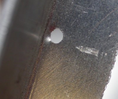
A couple of the pre-punched holes on the upper 79-L1 angles seem impossibly
close to the angle web. Emailed Bryan about it.
The first thing I tried to do, to bend the 79-L1 top angles to match the
profile of the top edge of the console outline and cleco the L1s into place,
got halted because hole #2 on each side isn't even close to aligning,
although the rest seem to line up. Emailed Bryan about it. Turns
out these 2 parts don't go together quite like this. The side panel
remains straight, and the top angle goes out away from side skin, then bends
back again and parallels it.
Nov 29 - trying to decipher
console plans and identify console kit parts. Start assembling console.
Temps in 50s; incredible
3.0 hr
Nov 30 - email Bryan about
identifying some of the parts & asked about why such thick metal used.
Good prompt responses from Bryan. Labeled console parts, using info I
got back from Bryan. Cleco console parts together. Have a couple
more questions for Bryan. Nearly 60 degrees today; I love it.
2.25 hr
Here are most of the console parts clecoed together. The quadrant and
MT prop controller are laid in place. I don't understand why the brackets fwd of the quadrant
are not parallel to quadrant vertical center line. I may not need them
at all for my setup. Emailed Bryan about
that & a couple other questions. Quite unfortunately, the console is too narrow to put the
prop controller in horizontally, so I may need to move the R2 brackets aft
and put it in turned lengthwise, as shown. Or I may put it in fwd of the
quadrant, as long as it won't interfere with the Andair fuel valve parts.
DEC UPDATE - I decided to not use those fwd brackets and related
parts, as they are unnecessary for my application, and they interfere with
the brackets on the quadrant.
 Reaming one of the gear mount frame holes on the lower RT side. The
black is heatshrink I slid into the aft spar hole to help stabilize the
reamer and to protect the spar hole. It was a perfect snug slip fit
between the spar hole and the reamer shaft. I ground a square end onto
each reamer and turned it slowly & carefully by hand with a small adjustable
wrench, while pushing the reamer fwd into the gear mount frame. It's
too close to the floor to get any sort of drill in there, plus doing it by
hand, while much slower and more tedious, offers more care and control.
I see no sign (like removed gold anodizing) that any cutting is taking place
inside the spar holes.
Reaming one of the gear mount frame holes on the lower RT side. The
black is heatshrink I slid into the aft spar hole to help stabilize the
reamer and to protect the spar hole. It was a perfect snug slip fit
between the spar hole and the reamer shaft. I ground a square end onto
each reamer and turned it slowly & carefully by hand with a small adjustable
wrench, while pushing the reamer fwd into the gear mount frame. It's
too close to the floor to get any sort of drill in there, plus doing it by
hand, while much slower and more tedious, offers more care and control.
I see no sign (like removed gold anodizing) that any cutting is taking place
inside the spar holes. 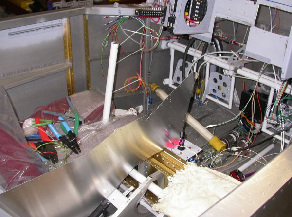 This is what the outline of the console will basically look like, with one side panel laid
in place. Upper front tip of each panel got crunched in shipping, but
I hammered them out flat. In upper center of pic, you can see the
This is what the outline of the console will basically look like, with one side panel laid
in place. Upper front tip of each panel got crunched in shipping, but
I hammered them out flat. In upper center of pic, you can see the
 A couple of the pre-punched holes on the upper 79-L1 angles seem impossibly
close to the angle web. Emailed Bryan about it.
A couple of the pre-punched holes on the upper 79-L1 angles seem impossibly
close to the angle web. Emailed Bryan about it.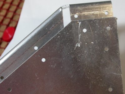 The first thing I tried to do, to bend the 79-L1 top angles to match the
profile of the top edge of the console outline and cleco the L1s into place,
got halted because hole #2 on each side isn't even close to aligning,
although the rest seem to line up. Emailed Bryan about it. Turns
out these 2 parts don't go together quite like this. The side panel
remains straight, and the top angle goes out away from side skin, then bends
back again and parallels it.
The first thing I tried to do, to bend the 79-L1 top angles to match the
profile of the top edge of the console outline and cleco the L1s into place,
got halted because hole #2 on each side isn't even close to aligning,
although the rest seem to line up. Emailed Bryan about it. Turns
out these 2 parts don't go together quite like this. The side panel
remains straight, and the top angle goes out away from side skin, then bends
back again and parallels it.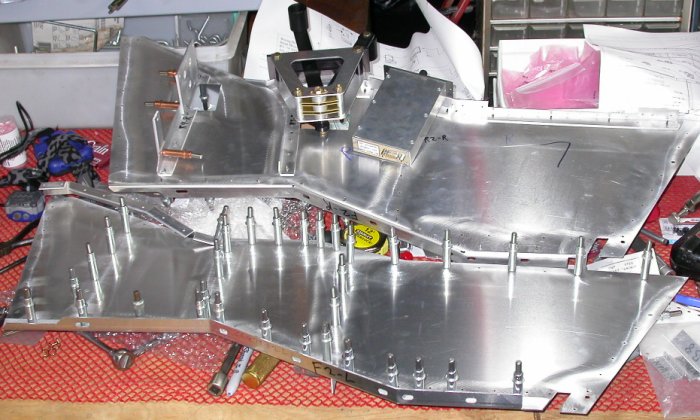 Here are most of the console parts clecoed together. The quadrant and
MT prop controller are laid in place. I don't understand why the brackets fwd of the quadrant
are not parallel to quadrant vertical center line. I may not need them
at all for my setup. Emailed Bryan about
that & a couple other questions. Quite unfortunately, the console is too narrow to put the
prop controller in horizontally, so I may need to move the R2 brackets aft
and put it in turned lengthwise, as shown. Or I may put it in fwd of the
quadrant, as long as it won't interfere with the Andair fuel valve parts.
DEC UPDATE - I decided to not use those fwd brackets and related
parts, as they are unnecessary for my application, and they interfere with
the brackets on the quadrant.
Here are most of the console parts clecoed together. The quadrant and
MT prop controller are laid in place. I don't understand why the brackets fwd of the quadrant
are not parallel to quadrant vertical center line. I may not need them
at all for my setup. Emailed Bryan about
that & a couple other questions. Quite unfortunately, the console is too narrow to put the
prop controller in horizontally, so I may need to move the R2 brackets aft
and put it in turned lengthwise, as shown. Or I may put it in fwd of the
quadrant, as long as it won't interfere with the Andair fuel valve parts.
DEC UPDATE - I decided to not use those fwd brackets and related
parts, as they are unnecessary for my application, and they interfere with
the brackets on the quadrant.