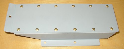
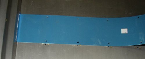
 F741 tunnel
cover completed.
 APRIL, 2003 fuselage work - part 1
Apr 1 - Completed plane and took it out for a ride. April Fools! Redrilled F741 holes to #30, reprimed holes, and riveted F741 tunnel cover together. Started on forward cabin covers. It started SNOWING again! Laid out, clecoed, drilled, deburred F982 C, D, E and F983 A, C. 6.5 hr
 F741 tunnel
cover completed.
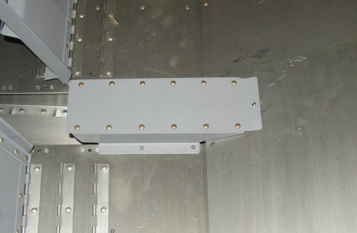 F741 tunnel
cover in place forward of seats.
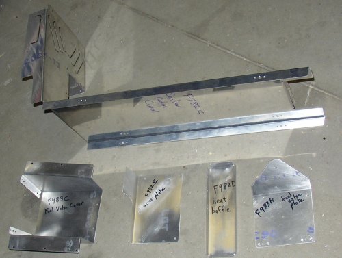 Here are the forward covers, laid out, clecoed, drilled, deburred, and
scuffed for primer. Will finish scuffing and prime tomorrow.
Also, many of these pieces are thin 0.020" sheet metal, and have
nutplates attached, so I wrote Van's and asked how to get nutplates on with
426 flush rivets on such thin material.
IMPORTANT NOTE: As I found out later (See my June 28 notes), the F-782C Center Cabin Cover and F-783C Fuel Valve Cover will need to be significantly modified if you are running a fuel injected plane. So, don't bother with those 2 pieces until you get the FI fuel pump kit. The details on the modifications will come with the FI pump kit. If you're going FI, you might as well order the FI pump kit now.
Apr 2 - SNOWING AGAIN! Got a late start in middle of afternoon, after sleeping late and running errands. Got advice from Van's about dimpling the nutplates, so I dimpled them and the F982/982 Forward Covers. Primed the parts and riveted them. Most of the riveting on these was for nutplates, with just two pieces riveted together. Opened up the cabin heat louvers on the F982C Center Cabin Cover. 3.5 hr
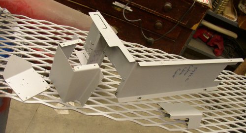 Here are the
F982 and 983 parts, primed and all nutplates riveted on.
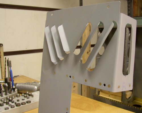 Bent the
louvers open for the cabin heat outlets. I did this after painting
because I thought it would be easier to get good primer coverage when they
were flat. Of course, the tradeoff was that I did this wrestling with
them on the fresh paint. But the paint seemed to stand up to it pretty
well, and can be touched up without any problem.
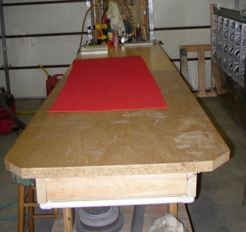 After opening
the louvers, I decided to clean up the workbench. Doing the louvers
was a bit of a hassle because I was wrestling with the big, awkward, floppy
F982C on the bench while it was completely covered with multiple layers of tools, parts, and
hardware.
Apr 3 - It's SNOWING again! It's snowed every day this week. Will this horrendous winter never end? Started in on electric flaps. Installed the WD-613-EF flap actuator weldment and fabricated the plastic bearing blocks to hold it in place. Had problems with a bend in the 613 weldment. Milled 0.110" off the bottom of the F-680 flap bearing block to get a better fit. Then found that it slid back & forth 1/16" when rotating the weldment arm, indicating a bend in it. Emailed Van's about it. Riveted the baggage tunnel cover nutplates. Fabricated F-766C plate and F-766B angle. Fabricated F-785B angle. Got it nearly done and realized the Quick Build kit came with that piece already done and installed. Fabricated F767 attach plate. Fabricated F758L&R and drilled & clecoed them to the F-766A flap actuator channel. Drilled and countersunk F-766A for nutplates. Fit up the F-766A and F-767. Spent quite awhile screwing around getting the nutplates to fit on the F-767 and countersinking for the nutplate flush rivets. Ended up putting them on differently than specified in plans, but I think it's better. Screwed up one rivet countersink closest to the bend, but not bad enough to redo it. Partially primered the F-767 and riveted the nutplates on. Worked to 0415. 11.5 hr
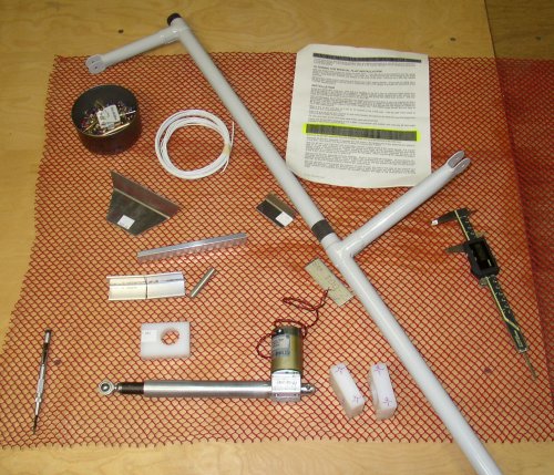 Here are
some of the parts for assembling the electric flaps.
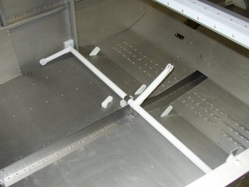 Here is
the flap weldment installed in the bearing blocks.
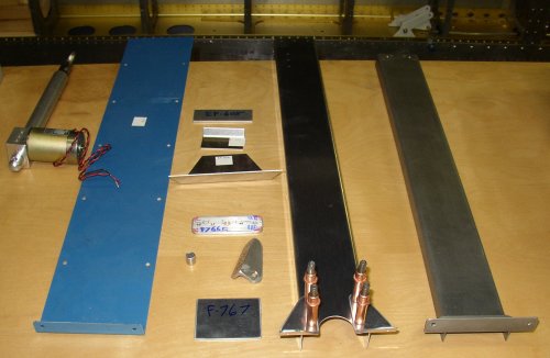 Here are
the electric flaps parts after fabrication of all the little pieces and starting
to cleco things together.
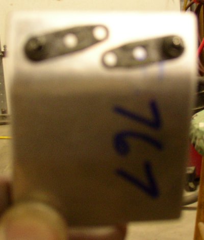 Poorly
focused picture of the nutplate layout I used on the F-767. I thought this
layout was better than trying to put a flush rivet right in the middle of the
bend.
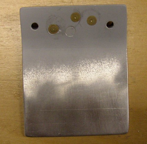 I had to
get the nutplates riveted in so I could put this piece, the F-767, in place with
screws and proceed with the layout of the rest of the electric flap parts, so I
just primered it enough to get the nutplates in and riveted.
Apr 4 - Got another 10" of SNOW overnight, and it's snowing like hell all day. Resume flap actuator assembly. Drill & cleco F-766 to F-767 to F-705 bulkhead. Mount flap actuator motor to F-766A assembly. Install F-766 assembly and F-785A . Attempt to fit F-760 LT & RT Flap Actuator Covers. Both have poor fit. I called Van's about it, but they were close to closing, so I sent them an email with pictures. See details below. Spent 3 hours sending emails to Van's and updating this web site with last few days' details. Dismantle flap actuator parts and prep for primer. Prime parts. 5.0 hr + 3.0 doc
 Here are the F-766A, flaps actuator motor, and all supporting parts, ready
to install.
 Here is the electric flaps actuator motor installed in the F-766A Flap Actuator
Channel with all the supporting parts.
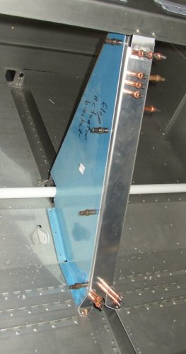 Here's the flap
actuator mostly in place. The cover, still with the blue wrap on, isn't fitting right,
so I emailed Van's about it. The problem is that when it is
clecoed in place on the F-766A, as shown, it doesn't sit on the floor correctly.
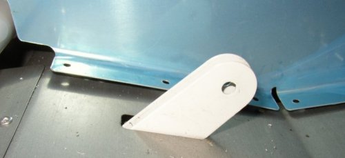 Here's the
problem with the F-760 Flap Actuator Covers. They don't sit on the floor
correctly. We'll see what Van's says about it. In the meantime, I
have plenty of other things to work on.
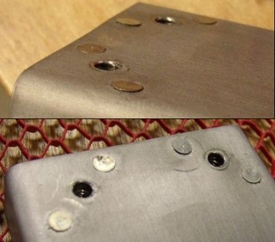 Here is the only
bad work I have seen on this QB kit. It's the nutplate riveting job on the
F-785A Backrest Brace. I wrote to Van's about it.
Apr 5 - Rivet F-766C plate to F-766A, with proper rivets. Mount 766 assy for 767 alignment. 3.5 hr
 Had to
drill out these four 470 rivets on the 766A to 766C plate, and put in the proper
426 rivets. I couldn't find the spec in the plans, so I had gone ahead
with it. Then I later found the rivet specs for this while looking for
2 other fastener specs I never did find.
Apr 6 - too tired to write up details for last 2 days. It's already 0400 and I've been doing paperwork on this project and emailing Van's about more issues since I quit working on the plane at 0200. Details later. Fabricate F-759A flap rods. Work on F-748 tunnel cover. Study plans to see where to go next. Start on rudder and brake pedals. Debur F-6117-BPP pedals and F-6117A plate. Fabricate four F-6117C angles. Clamp, drill, cleco, debur brake pedal parts. Work on F-6118 rudder pedal brace. Work on F-6116 rudder pedal outboard bearing blocks. Lay out WD-655 L & R. 9.5 hr + 2.0 doc
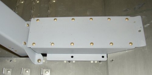 Bad fit on
F-741. Emailed Van's about it. I ended up fixing this on the 8th
by cutting the lip off the rear (LT side) of the F-741.
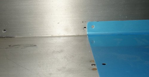 Bad fit on
F-748. Emailed Van's about it.
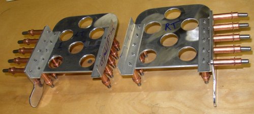 Brake
pedal components all fabricated and clecoed together.
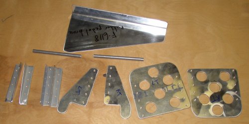 Brake
pedal components deburred.
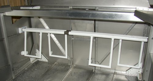 Rudder pedals installed. Lots of screwing around here to get
everything right.
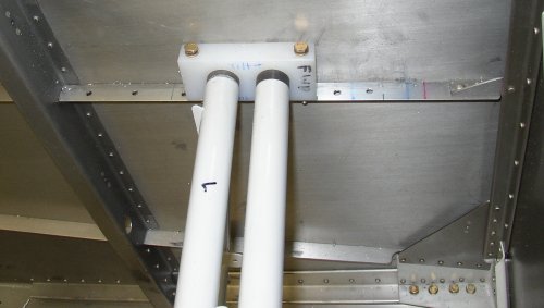 I
made several adjustable positions for the rudder pedals.
Apr 7 - I've sure been making lots of little screwups the last couple days. Fortunately, all are fixable without too much trouble. Worked on F-6118 rudder pedal brace layout. Lay out F-6115 center rudder bearing block. Lay out F-6118 and fit to bulkhead. Got email from Ken at Van's saying cause of several fit problems is that I made the F-767 inverted. Started removing and remaking it. Thought I had to reposition both F-758 pieces, too, but after I drilled out their rivets, realized they were OK, so re-riveted them. Drilled the new 767 and used previous holes as a guide. Turned out that, due to slightly different geometry, holes were wrong, so I chucked the 767 into the mill and slotted the screw holes. By 2200, finally got that mess unscrewed. Trim F-741B rear so it fits next to F-766A correctly. Resumed F-6118 layout. Found out it isn't long enough to use the rearmost pedal adjustment holes I made last night. Oh well - doesn't hurt anything. Drilled holes in F-705 frame from #19 to #12 to end touchy fitting of F-766. Skipped 6118 for now and resumed the F-760 L & R flap actuator covers and F-748 cover. Put nutplates on F-785A post so F-760 covers will screw on OK. Did metal prep on F-760s and brake pedal parts. Back to the 6118 and making new closer adjustment holes for bearing blocks. Debur holes in airframe and 6118. Lay out lightening holes in 6118. 14.0 hr
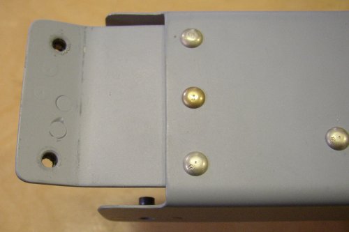 Ken at Van's
emailed me back about the F-766A and F-760 fit problems I was having.
It turns out I transposed which set of holes were supposed to go next to the
bend on the F-767. The bend is supposed to be down next to the edge of
the F-766A, where the 3 rivets are. I'll make a new F-767 from
stock.
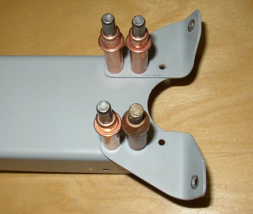 After making the
new F-767, the fit wasn't quite right, and I thought I'd have to readjust
the location of these F-758 legs. But, after drilling out the rivets,
I realized they were OK, and the fit adjustment was in the exact placement
of the F-767 on the F-766A. So, I re-riveted the legs back on.
At least I do a nice clean job of removing rivets.
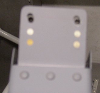 Another
screwup while fixing the previous screwup with the F-767. I made the
nutplate holes to match the hole on the previous screwed up F-767. But
I subsequently found they were off, due to the difference in the F-766A
angle, so I just elongated them. All they are is an access hole for
the nutplate, so structural integrity is not affected. Nice looking
work, though, eh? Oh well, I just have to accept it and move on, as I
sure as hell don't want to redo the F-767 AGAIN. Sorry about the
focus. Sometimes the camera doesn't get a good focus if things are too
close, and it looks OK in the viewing screen.
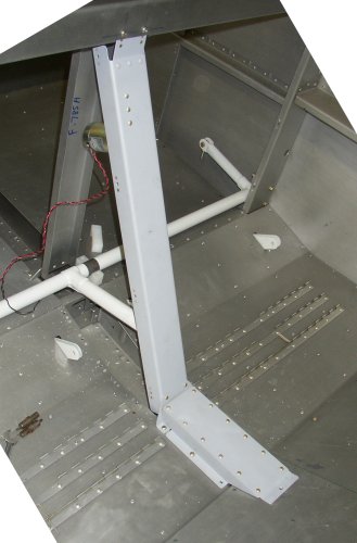 Here are
the F-767, 766A, 741 assemblies, all finally fixed and in place. Even
after fixing the F-767, I still had to trim off all of the rear of the F-741
to get it to fit forward of the F-766 and F-758R&L.
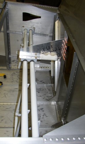 The rudder pedal center bracket, clecoed into place and drilled at multiple
locations to match each of the rudder pedal holes I'd previously laid out on
each side.
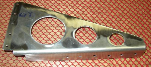 Here is the rudder pedal center bracket, deburred and ready to prime.
Apr 8 - Keeping up with this web site has been difficult the last few days. I work on the plane parts every chance I get, and then I'm too tired to invest another hour or two on putting the details in. I guess I'd rather be spending my time working on the plane, rather than writing about it. I've been taking pictures, though, and putting them in. Tonight, after watching Leno and Charlie Rose, I didn't go back into the garage. I decided to remain here at the computer and try to get the details from the last few days put in here. As mentioned earlier, I've had lots of screwups lately, including several today. I've got to be more careful, before I make a more serious mistake that will require me to have to order a replacement part and wait a week or more for that to come. Put brake pedal together. Forgot to trim corners of F-6117C angles, so I cut them off and reprimed. Then, just before I started riveting them together, I realized they should be 426 rivets, not 470, so I drilled countersink holes. See details below regarding that clusterf-. Finally riveted brake pedals together. Spent another 2 hr (which I have not been logging as "time" - perhaps I should be) working on web site. 4.0 hr + 2.0 doc
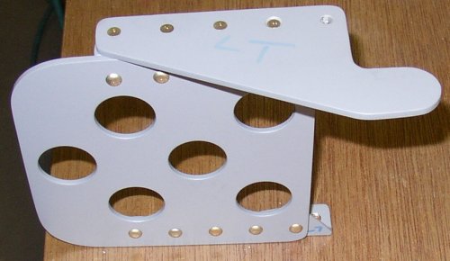
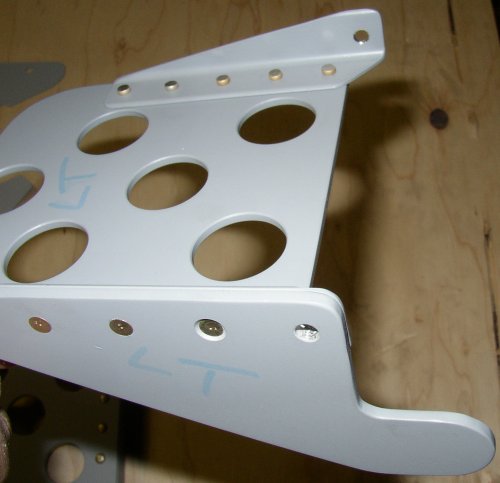 Here is
the LT brake pedal, showing 4 fixed screwups. The first 2 were just
things I forgot to do before priming, so I had to do them, then
reprime. They are the 2 brake pivot holes at the RT top and bottom of
this picture. The other was I forgot to remove the inside corners of
the 4 angles, as seen at the top of this picture, just under the pivot
hole. They were supposed to have been removed to save weight.
All 4 corners probably weighed a gram, but I noticed I hadn't removed them
after I'd primed the angles and was ready to rivet, so I cut them off and
reprimed again. The worst screwup was the one 426 "flush"
rivet in the RT foreground. I had initially thought these rivets were
to be 470 universal rivets. I double-checked after priming and just
before riveting, and realized all these rivets were supposed to be 426 flush
rivets. So, I had to countersink the holes, then reprime again.
As you can see, this rivet is way deeply set into the bracket arm. I
didn't check my countersink cage before countersinking the holes, because
it's normally left set correctly. However, after I countersunk the
holes on the RT pedal, I noticed they were too deep. I realized I had
forgotten to reset the cage to my "normal" setting after setting
it 10 notches deeper so a dimple would fit better into the countersink hole
I'd previously worked on. However, when I corrected the cage for the
LT pedal, I went 10 clicks the WRONG way, so this hole is 20 clicks too
deep. Grrrr! Rather than trash the arm and redo it, I cut down a
rivet set to the same diameter as the 426-4 rivet head and squeezed it
inside the countersink hole. It seemed to work OK. The metal on
the arm is thick enough to get away with it, and I don't think it will
present any structural problems. This is an example of why I call
myself a "pragmatic perfectionist". I go to great lengths to
strive for perfection, but I can reluctantly accept it when something is not
perfect. All 4 of the holes on the RT pedal were 10 clicks too deep,
and I used the same modified set to squeeze all of them. It's hardly
noticeable on the RT pedal, though.
 When I
realized I hadn't countersunk the bracket arm for flush rivets, I also
realized the 5 rivets on each side of the pedal, to the angles on each side,
were also supposed to be 426 flush rivets. But, after thinking about
it, I decided I really preferred the 470 universal rivets here anyway, so I
didn't countersink the pedals, and went ahead with the 470 rivets.
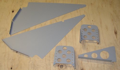 Here are the brake pedals, FINALLY completely assembled properly, as well as
the rudder pedals center brace and the 2 F-760 flap actuator covers.
Once the F-767 was corrected, the F-766A sat in place OK, and so did the
F-760 covers. Hopefully, this is the end of my screwup days.
Between all the 766/767 screwups and all my screwups with these brake
pedals, I have had enough of that!
Apr 9 - Worked very late again on plane (0300). Still too busy with working on plane to fully write up details or to calculate hours spent. I'm about a week behind on that by now. Mounted brake pedals to rudder pedals. Riveted rudder pedal brace into place. Started building elevator bellcrank. F-748 fit OK after I'd enlarged the screw holes form #19 to #12. I think I will do this on all the cover panels from now on. Bandsaw ate my 3/8" tubing for F-635C spacers, so I polished up the outside of the tubing. It's only for spacers, so polished scratches in outside should not be a factor. Cut F-635C spacers on the lathe after that. Spray primed inside of wing aileron control rods, then another hour or 2 on the computer, processing photos and photo captions. 8.0 hr + 2.0 doc
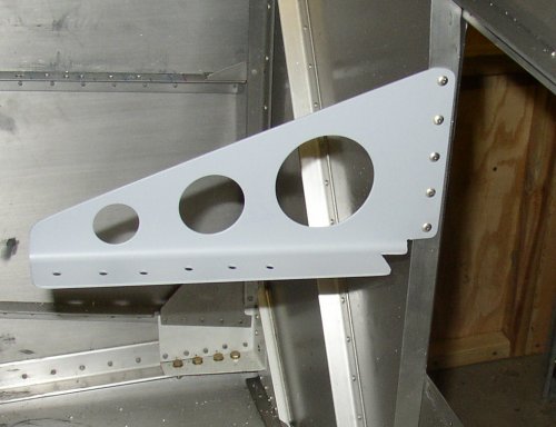 Here is the rudder pedals center brace, riveted in place. I couldn't
get a squeezer on it, so I had to use a gun.
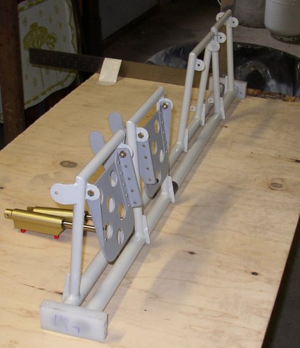 Laying
out the brake pedal positioning, so both are parallel.
 Brake and
rudder pedals completely installed and ready to set aside for later
installation into fuselage.
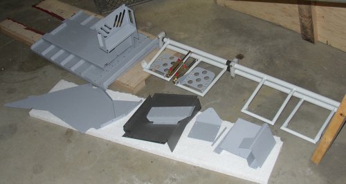 Here
is my pile of completed parts, mostly panels and covers, waiting for their
moment to be installed.
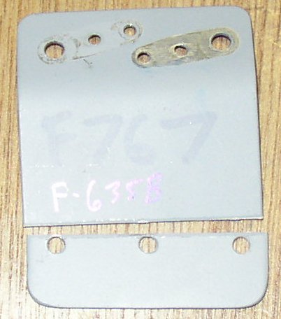 I had to make
a spacer for the Elevator Bellcrank, so I was able to reuse the old
discarded F-767.
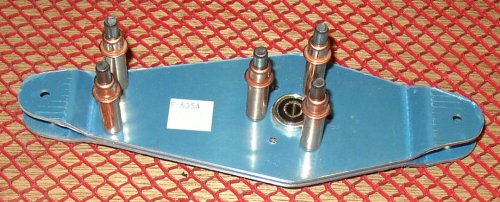 Here is the elevator bellcrank, spacer, and bearing, clecoed together.
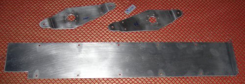 Here are the elevator bellcrank parts, as well as the F-748 tunnel
cover. I finally got the 748 to fit by drilling the holes to #12 and
removing the poor-fitting rear baggage compartment cover.
 These are the 2 bellcrank bushings I had to make. The directions said
to make sure the ends are square, so I wanted to cut them off the stock tube
with my bandsaw, rather than with a hacksaw. Unfortunately, the stock
piece was only 4" long, so there wasn't enough material for the bandsaw
clamp to grip it. So, I decided to try to hold it in place by
hand. As soon as the blade dropped onto the tubing, it ripped it out
of my hand and then the tubing started spiraling under the blade. By
the time I got the bandsaw shut off, it had chewed up the entire exterior of
the tubing. I am supposed to have two 4" pieces of this tubing,
but I couldn't find the other piece, so I must have already used it
up. I didn't take a pic of it then (much worse) but I polished the
outside quite a bit on the Scotch-Brite wheel until the surface looks like
it does here. Since these are just spacers for a bolt, structural
integrity is not affected. I tried to cut off a piece (11/16 length)
with a hacksaw and got the expected end that was nowhere near square.
So, I chucked the tubing up in my metal lathe and cut them off with that, to
get perfectly square ends. I spent quite a bit of time screwing with
these bushings.
 These are the wing aileron control rods. They're about 5' long.
I finally got around to priming the inside of them, and will prime the
outside tomorrow, along with the elevator bellcrank parts and F-748.
Apr 10 - Slept very late. Finally got started around 1500. Primed bellcrank, F-748 tunnel cover, and aileron control rods. Assembled elevator bellcrank and riveted it together. Tapped out the paint on the aileron control rod threads. The bellcrank didn't fit into its space, so I had to chuck the spacers into the lathe and remove a total of 0.050" off each one. Installed bellcrank. Cleaned up workbench and studied plans for next task. Built the F-789 forward elevator control rod. Built the F-665 control column pushrod. Started putting control sticks in. When I went to take out the removeable floor rib sections to install the control column , I found that, for some very odd reason, they used nuts to hold the screws in, rather than the usual nutplates. I was going to install nutplates myself, but I didn't have enough of the right type, so I held off on it. I spent a bunch of time carefully adjusting the length of the control stick mount points and the bushing that goes in there. I calculated the length needed and trimmed the bushings on the lathe. By 0400, I had both sticks installed. 11.0 hr
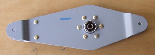 Elevator bellcrank riveted together.
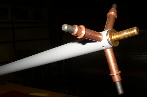 Forward elevator control rod clecoed and ready to be riveted.
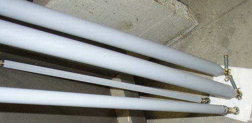 Completed forward elevator control rod, control column pushrod, and aileron
control rods.
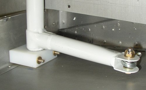 Reversed bolt layout at each end of flap actuator weldment. Note bolt
drilled for castle nut and cotter pin. The plans called for a locknut,
but I as far as I know, when a bolt has a rotating part on it, it's supposed
to have a cotter pin, not a locknut. Van's has several like
this. I plan to write them and ask why they do this.
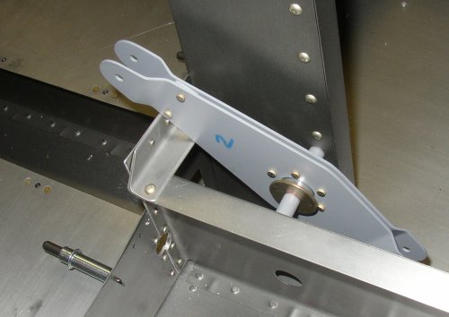 Here is the installed elevator bellcrank.
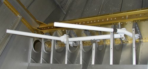 Here
are the control sticks and the horizontal control column installed.
AUGUST, 2009 UPDATE - If you're going to be installing grips with switches, especially Infinity Aerospace grips that require mods to the stick, BE SURE to do this NOW, not after you've installed the sticks. See August interior page for details
continue to April Part 2
BACK TO MY RV BUILDER'S HOME
BACK TO BRIAN'S HOME